Secondary gasification treatment method for oil residue caused in gas production

A technology of secondary gasification and treatment method, which is applied in the petroleum industry, manufacture of combustible gas, energy input, etc. It can solve the problems of low carbon conversion rate, small gas production, high cost, etc., and achieve high gasification efficiency and high gasification efficiency. The effect of high and effective utilization rate improvement

Inactive Publication Date: 2014-01-29
杜维兴
View PDF3 Cites 2 Cited by
  • Summary
  • Abstract
  • Description
  • Claims
  • Application Information

AI Technical Summary

Problems solved by technology

The old method has low carbon conversion rate, small gas production, high pollution, and the cost of achieving environmental protection is too high

Method used


Image

  • Secondary gasification treatment method for oil residue caused in gas production
  • Secondary gasification treatment method for oil residue caused in gas production

Examples


Embodiment 1

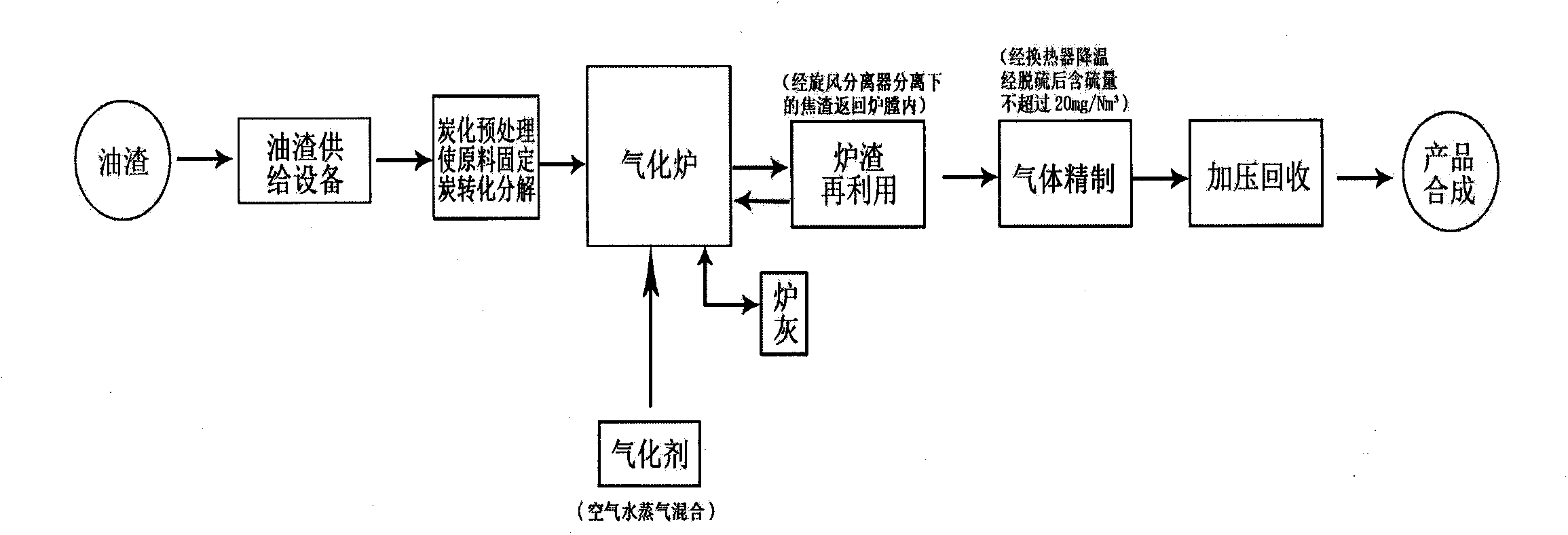
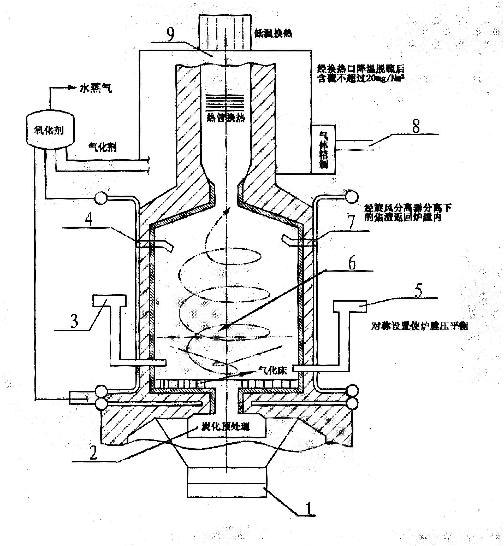
[0022] A raw coal gasification oil residue treatment method, as follows: the oil residue raw material with a diameter of less than 10 mm is transported from the feed port 1 to the oxygen-free carbonization furnace 2 coal hopper, and the oil residue raw material is further gasified into CO and CH 4 and H 2 The mixed gas is then sent to the cone section at the bottom of the gasifier to react with the gasification agent. The gasification agent is air, water vapor mixture or oxygen-enriched air water vapor mixture. The gasification agent is supplied from the primary tuyere 3 and the secondary The tuyere 5 enters the hearth 6 of the gasifier. Before the gasification agent enters the hearth 6, it exchanges heat with the coal gas discharged from the furnace in a high-temperature heat exchanger. The temperature of the gasification agent rises to 750°C. The pressure at the top of the gas furnace is 15Kpa and the temperature is 980°C. , the coal gas flows out from the top of the gasifie...

Embodiment 2

[0024] Parameters of oil residue gasification system

[0025] Gas output 8500-11000Nm 3 / nY;

[0026] Oil residue gas production 1500Nm 3 / nY;

[0027] Calorific value of gas 1300-1600cal / Nm 3 ;

[0028] Calorific value of oil residue gas 800-1100cal / Nm 3 ;

[0029] Steam output 1.5-2 tons, pressure 0.5MPA;

[0030] Coal consumption 2.5-3 tons;

[0031] Oil residue consumption is 3 tons.

[0032] Table 1 is the gasification system parameter list

[0033] General fuel

tar residue

Furnace granularity

<10mm

Vaporization rate

1.5-2.0Nm 3 / Kg

SO 2 emissions

3

steam volume

0.7-1 ton

Dust emissions

3

[0034] Table 2 is the volume percentage comparison table of various gases of gas and oil residue (percentage)

[0035] Element


PUM

PropertyMeasurementUnit
diameteraaaaaaaaaa
particle sizeaaaaaaaaaa

Abstract

The invention discloses a secondary gasification treatment method for oil residue caused in gas production. The secondary gasification treatment method for oil residue caused in gas production comprises the following steps: delivering an oil residue raw material with the particle diameter of 10mm below to an oxygen carbonizing furnace for carbonizing treatment, further gasifying the oil residue raw material, then transmitting the mixture gas into a cone section at the bottom of a gasification furnace so as to react with a gasifying agent, wherein the temperature of the gasifying agent is 750 DEG C, the pressure and temperature of the top of a gas furnace are respectively 15Kpa and 98 DEG C; flowing the gas out to enter a primary cyclone separator, returning the separated residue ash back to the hearth of the gasification furnace through a return pipe, and entering the gas into a dry type dust collection system after being subjected to dust collection treatment by a secondary cyclone separator, then cooling the gas again by a heat pipe exchanger, and recovering the desulfurized gas in a pressurization system. According to the secondary gasification treatment method, the gasification efficiency is high, the fluidization quality is improved, the flying ash quantity, flying as carbon content, ash slag carbon content in the gas can be greatly reduced, and the effective utilization rate and gasification efficiency of the oil residues can be improved.

Description

technical field [0001] The invention relates to a secondary gasification treatment method for oil residue in coal gas production. Background technique [0002] The new oil residue treatment process is developed from the circulating fluidized bed gasification (CFBG) technology. Fluidized bed gasification technology is to gasify the solid oil residue particles in the furnace bed after being fluidized by gas. In the fluidized bed gasification furnace, the gas agent (air, water vapor mixture or oxygen-enriched air, water vapor mixture) Passing through the hearth at a higher speed, the gaps between the oil residue particles increase, and the bed expansion height increases. This state of the bed is called solid fluidization, that is, solid particles have fluid characteristics. The old method has low carbon conversion rate, small gas production, high pollution, and the cost of achieving environmental protection is too high [0003] When the particles circulate between the fluidi...

Claims


Application Information

Patent Timeline
Patent Type & Authority Applications(China)
IPC IPC(8): C10J3/66C10J3/84
CPCY02P20/129
Inventor 杜维兴
Owner 杜维兴
Why Eureka
Try Eureka