Heating wire component in electronic cigarette and welding method of heating wire component

A welding method and heating wire technology, applied in the field of electronic cigarettes, can solve problems affecting the quality of heating elements, affecting product quality, and poor heating wires, and achieve the effects of pure smoke taste, ideal heating effect, and small resistance change

Inactive Publication Date: 2014-02-05
林光榕
View PDF9 Cites 9 Cited by
  • Summary
  • Abstract
  • Description
  • Claims
  • Application Information

AI Technical Summary

Problems solved by technology

[0002] In the prior art, the electronic cigarette heating element and the wire are welded by tin welding or copper capillary riveting. When tin is used as the solder for welding, tin will pollute the e-liquid and cause heavy metal pollution. This method does not Environmental protection is not hygienic, and the heating wire element is nickel-chromium alloy wire or iron-chromium-aluminum alloy wire. When the tube is riveted, since the thin copper tube is a relatively active metal material, this type of material is easily corroded by the e-liquid, causing the e-liquid to be polluted; in addition, due to the force of the riveting, the connection end of the heating wire is more mechanically crushed, resulting in heat Defective wire phenomenon, affecting product quality
It can be seen from the above that the existing heating element welding technology will make the smoke oil polluted, not environmentally friendly and hygienic, and affect the quality of the heating element, etc.

Method used


Image

  • Heating wire component in electronic cigarette and welding method of heating wire component
  • Heating wire component in electronic cigarette and welding method of heating wire component

Examples


Embodiment 2

[0036] Embodiment two: using a thermocouple welding machine as a laser spot welding machine, the implementation method steps are as follows:

[0037] 1. Adjust the machine: turn on the power switch, the thermocouple welding machine enters the standby state, press the "function key" on the control panel to enter the setting state, and the POWER state light starts to flash. Press the "+" and "-" buttons to adjust the energy required for welding the heating wire. According to the material and wire diameter of the heating wire, the energy needs to be adjusted. The general energy value ranges from 180 joules to 700 joules.

[0038] 2. Butt welding:

[0039] 2.1 Reliably connect the connecting clamp with the base metal;

[0040] 2.2 Turn on the power switch, the circuit starts to charge, the indicator light turns off, and the voltage reaches the set value when the indicator light turns red;

[0041] 2.3 Clamp the conductive wire 20 with welding pliers to realize electrical connect...

Embodiment 3

[0042] Embodiment 3: Using a precision resistance welding machine as a laser spot welding machine, the steps of the implementation method are as follows

[0043] 1. Precision resistance welding mechanical adjustment:

[0044] 1.1 Welding energy adjustment:

[0045] Press the "function key" on the control panel once in the standby state to enter the setting state, the POWER state starts to flash, press the "+ key" once to increase the welding energy by one, long press the "+ key" to increase the welding energy rapidly; press the "- key once "The welding energy is reduced by one, long press the "-" button to quickly reduce the welding energy. Press the "function key" four times to save the setting parameters and exit the setting state to enter the standby state. According to the material and wire diameter of the heating wire, the energy needs to be adjusted, and the general energy value ranges from 120 joules to 500 joules.

[0046] 1.2 Welding pulse adjustment:

[0047] Pre...

Embodiment 1

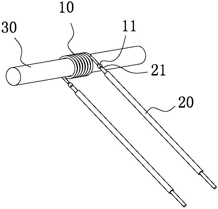
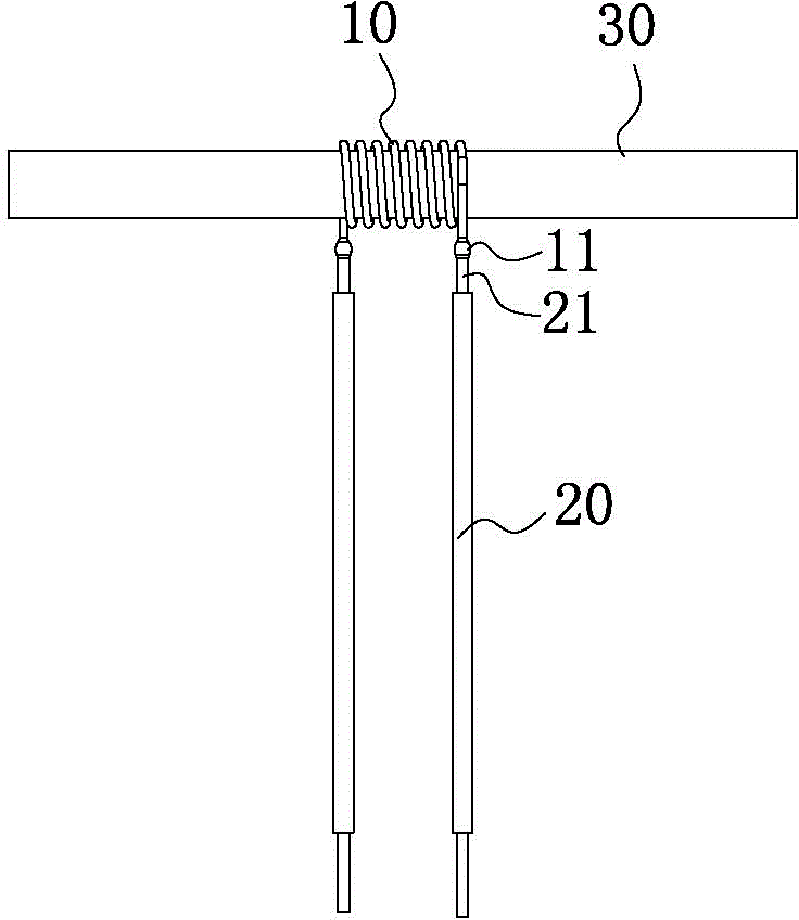
[0059] In Embodiment 1 and Embodiment 2, it is mainly operated manually, and auxiliary tools such as tweezers and scissors can be used. Use tweezers to twist and bind the stripped part of the conductive wire and the heating wire together, wrap the connecting end of the heating wire around the core wire of the connecting end of the conductive wire for 2-3 turns, and then cut off the excess stripped part to leave about 1.0mm.

[0060] Among them, the third embodiment realizes mechanical automation operation, and these methods all use laser spot welding to directly weld the heating wire and the conductive wire without adding any other auxiliary solder. The two ends of the heating wire 20 wound on the oil-absorbing rope 30 and the two conductive wires can be welded to complete the heating wire assembly according to the above process in sequence. After adopting the above scheme for welding, the present invention has the advantages of small and firm welding points after welding, and...


PUM


Abstract

The invention relates to the technical field of electronic cigarettes, in particular to a heating wire component in an electronic cigarette and a welding method of the heating wire component. The to-be-welded heating wire component in the method comprises electric leads and a heating wire which is wound on an oil suction rope. The method includes the following steps: step 1, removing outer skin of a connecting end of each electric lead to enable a core wire inside the corresponding electric lead to be exposed outside; step 2, electrically connecting one working electrode in a laser spot welder with the electric leads; step 3, enabling the core wire on the connecting end of each electric lead and a connecting end of the heating wire to be connected and to oppositely collide on another working electrode of the laser spot welder simultaneously, and enabling the laser spot welder to output current to integrally weld the core wire on the connecting end of each electric lead and the connecting end of the heating wire. After adopting the above scheme for welding, a welding point is enabled to be small and firm after welding, and faulty welding and false welding are avoided; resistance change is small, the welding point is free of heat energy conversion due to electrification and cannot be corroded by tobacco tar, and pure mouthfeel of smoke taste during smoking can be guaranteed.

Description

technical field [0001] The invention relates to the technical field of electronic cigarettes, in particular to a heating wire assembly and a welding method in the electronic cigarette. Background technique [0002] In the prior art, the electronic cigarette heating element and the wire are welded by tin welding or copper capillary riveting. When tin is used as the solder for welding, tin will pollute the e-liquid and cause heavy metal pollution. This method does not Environmental protection is not hygienic, and the heating wire element is nickel-chromium alloy wire or iron-chromium-aluminum alloy wire. When the tube is riveted, since the thin copper tube is a relatively active metal material, this type of material is easily corroded by the e-liquid, causing the e-liquid to be polluted; in addition, due to the force of the riveting, the connection end of the heating wire is more mechanically crushed, resulting in heat Defective wire phenomenon will affect product quality. I...

Claims


Application Information

Patent Timeline
Patent Type & Authority Applications(China)
IPC IPC(8): A24F47/00B23K26/22B23K101/32B23K103/18A24F40/10A24F40/46
CPCA24F40/46A24F40/10
Inventor 林光榕
Owner 林光榕
Why Eureka
Try Eureka