
Manufacturing method for light-blocking type micro-electro-mechanical variable light attenuator

A manufacturing method and micro-electromechanical technology, applied in the direction of optomechanical equipment, coupling of optical waveguides, and photoplate-making process of pattern surface, etc., can solve the problems of complicated processing technology, difficult integration, low yield rate, etc., and achieve simple process steps , Simplified alignment and assembly, Low cost effect

Active Publication Date: 2014-02-12
INST OF SEMICONDUCTORS - CHINESE ACAD OF SCI
View PDF4 Cites 6 Cited by
  • Summary
  • Abstract
  • Description
  • Claims
  • Application Information

AI Technical Summary

Problems solved by technology

[0007] Aiming at the shortcomings of the traditional variable optical attenuator, such as large volume, high cost, and difficulty in integration, and the problems of complex processing technology and low yield of the existing light-shielding variable optical attenuator, the present invention proposes a light-shielding micro-electromechanical The production scheme of the variable optical attenuator is produced by micro-nano processing technology, the process is simple, the production precision is high, and it is easy to integrate

Method used


Image

  • Manufacturing method for light-blocking type micro-electro-mechanical variable light attenuator
  • Manufacturing method for light-blocking type micro-electro-mechanical variable light attenuator
  • Manufacturing method for light-blocking type micro-electro-mechanical variable light attenuator

Examples


Embodiment Construction

[0032] In order to make the object, technical solution and advantages of the present invention clearer, the present invention will be further described in detail below in conjunction with specific embodiments and with reference to the accompanying drawings.

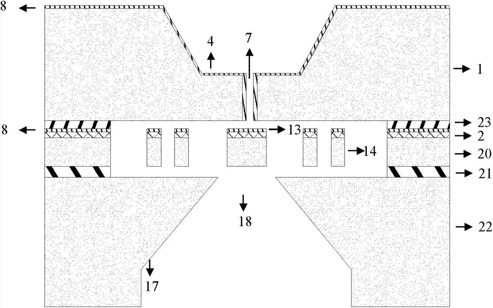
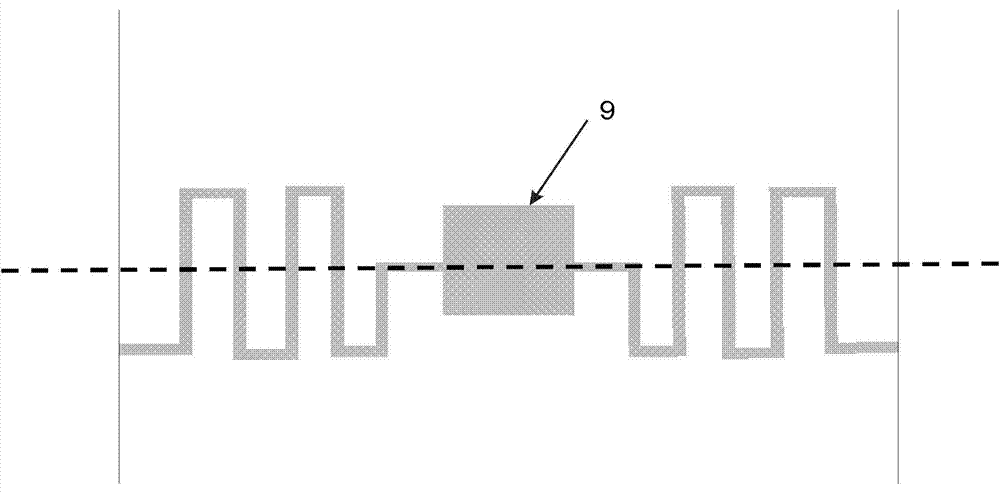
[0033] figure 1 A structural diagram of a light-shielding micro-electromechanical variable optical attenuator proposed by the present invention is shown. Such as figure 1 As shown, the light-blocking micro-electromechanical variable optical attenuator specifically includes: a fixed light-blocking plate and a movable light-blocking plate, the fixed light-blocking plate and the movable light-blocking plate are respectively made of substrate I and substrate II, and the fixed light-blocking plate and the movable light-blocking plate The light barrier is bonded to make a variable optical attenuator. The substrate I includes a silicon wafer, an SOI sheet containing a silicon oxide intermediate layer and a single crystal silic...


PUM


Abstract

The invention discloses a manufacturing method for a light-blocking type micro-electro-mechanical variable light attenuator. The method is based on micro-nano machining technology, bulk silicon machining technology is adopted to manufacture a fixed light-blocking board and a movable light-blocking board of the variable light attenuator, light-blocking materials are deposited on the fixed light-blocking board and the movable light-blocking board, so that the blocking and limiting effects on light beams are achieved; a light-permeable hole is formed in the fixed light-blocking board and is used for constraining the size of a light spot and limiting the diffraction of light. Technologies such as photoetching and corrosion are used for manufacturing the movable light-blocking board of the light attenuator so as to enable the movable light-blocking board to be capable of carrying out linear motion under the action of external driving force, and accurate adjustment of transmitted optical energy is achieved through the control over the position of the movable light-blocking board; finally, wafer level bonding integrates the fixed light-blocking board and the movable light-blocking board of the variable light attenuator, and controllable adjustment of the transmitted optical energy is achieved. By means of the method, the ordinary micro-nano machining method is adopted, technologies are mature and reliable, manufacturing accuracy is high, cost can be greatly reduced, and the manufacturing method for the light-blocking type micro-electro-mechanical variable light attenuator is suitable for scale production.

Description

technical field [0001] The invention relates to the field of MEMS manufacturing and engineering, in particular to a method for manufacturing a light-shielding micro-electromechanical variable optical attenuator. Background technique [0002] As a component in optical fiber communication, optical attenuator can adjust the intensity of optical signal through the movement of optical components or the change of optical state under the action of external excitation (mechanical, electric, magnetic, etc.). The optical attenuator is one of the important optical passive devices in the optical communication system. It can produce controllable attenuation in the optical network, and it can be well matched with other devices to achieve optical gain flatness, dynamic gain balance and transmission power balance. It has very important applications in the fields of communication, optical fiber analog signal transmission, optical sensor analog imaging, and optical fiber measurement. [0003...

Claims


Application Information

Patent Timeline
Patent Type & Authority Applications(China)
IPC IPC(8): G02B6/26B81C1/00B81C3/00
Inventor 毛旭魏伟伟吕兴东杨晋玲杨富华
Owner INST OF SEMICONDUCTORS - CHINESE ACAD OF SCI
Learn More