Novel modified A/O biological denitrification process

A biological denitrification and process technology, applied in the field of wastewater treatment, can solve the problems affecting the anoxic environment in anoxic tanks, low sludge concentration in aeration tanks, and long nitrification reaction time, and achieve strong shock load resistance and sludge. The effect of small production volume and low operating cost

Inactive Publication Date: 2014-02-19
天津市庆烁市政工程有限公司
View PDF0 Cites 3 Cited by
  • Summary
  • Abstract
  • Description
  • Claims
  • Application Information

AI Technical Summary

Problems solved by technology

The emission standards are becoming stricter, which also puts forward higher and higher requirements for the nitrification and denitrification process. To achieve a good denitrification effect in the traditional denitrification process, one must ensure a long enough nitrification time to meet the needs of nitrifying bacteria. A large amount of growth can achieve the purpose of nitrification reaction. However, the sludge concentration in the aeration tank of the traditional denitrification and phosphorus removal process is low, and the nitrification reaction time is long, requiring a large tank capacity, high civil construction costs, and a large area; second, aeration must be ensured. The reflux of the mixed liquid in the pool can return the nitrate nitrogen generated in the aerobic area to the anoxic area, so that the denitrification can proceed smoothly, but increasing the internal reflux ratio alone will significantly affect the anoxic environment of the anoxic pool, and affect the denitrification efficiency. Therefore, the development of a cost-effective denitrification process has become a hot spot in the current sewage treatment research.

Method used


Image

  • Novel modified A/O biological denitrification process

Examples


Embodiment Construction

[0011] The specific examples of the new improved A / O biological denitrification process are described below. Examples are illustrative, not restrictive, and the protection scope of the present invention cannot be limited with the following examples.

[0012] The present invention is clarified below in conjunction with figure and specific embodiment

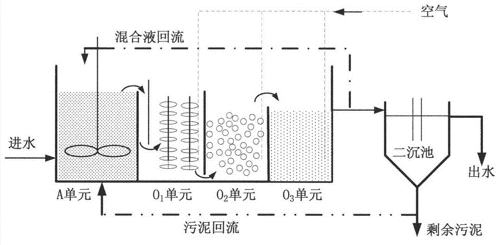
[0013] see figure 1 , figure 1 For this example, an improved A / O biological denitrification process includes anoxic pool and aerobic pool. The aerobic pool is divided into three sections, and the process flow is anoxic denitrification pool-biological contact oxidation pool-suspended biofilm pool- Activated sludge pool. The raw water enters from the bottom of the anoxic pond, and the raw water flows into the O in the aerobic pond by itself after the anoxic reaction. 1 District, in O 1 A baffle is set at the water inlet, so that the water inlet is from O 1 Enter the lower middle part of the district, O 1 District and O 2 The...


PUM


Abstract

The invention relates to a novel modified A/O biological denitrification process. The novel modified A/O biological denitrification process is characterized in that an aerobic tank for an A/O process is divided into three parts of O1, O2 and O3; and a residence time ratio of the three parts is O1:O2:O3=1:3:2. In the O1 part, a fixed filler is used to hang a membrane, sludge concentration of the O1 part is between 5,000-8,000 mg/L, sludge load is between 1.5 kg/(kg.d) and 5.5 kg/(kg.d); and BOD removal rate can reach over 50%. In the O2 part, sludge load is smaller than or equal to 0.25 kg/(kg.d); efficiency of nitrification is increased; suspending sphere-shaped filler is used to hang the membrane; a microcosmic anaerobic environment is formed in the biological membrane; and nitrification and denitrification can be realized at the same time, thereby facilitating removal of total nitrogen. In the O3 part, an activated sludge process is employed; sludge load is smaller than or equal to 0.1 kg/(kg.d), so that nitrification can be continuously carried out to make nitrification go thoroughly; and activated sludge metabolism in the region lies in an endogenous respiration period, so that sludge quantity produced by the process is reduced by over 40%. The aerobic tank is divided into segments and different biochemical processes are employed in different segments, so that denitrification efficiency can reach over 95%.

Description

technical field [0001] The invention relates to the technical field of wastewater treatment, in particular to a novel and improved A / O biological denitrification process for caprolactam chemical fiber wastewater. Background technique [0002] In caprolactam chemical fiber wastewater, ammonia nitrogen increases with the decomposition of caprolactam, which belongs to high ammonia nitrogen sewage. After a large amount of nitrogen in sewage is discharged into the water body, it will cause water pollution and eutrophication. With the content and value of the national discharge standard The continuous improvement of indicators and the gradual increase of assessment standards have put forward stricter requirements for nitrogen discharge standards. Therefore, nitrogen removal is the key and difficult point to achieve the discharge of this type of wastewater. [0003] The key to achieving discharge standards is the stable compliance of total nitrogen. Biological denitrification requ...

Claims


Application Information

Patent Timeline
Patent Type & Authority Applications(China)
IPC IPC(8): C02F3/30
Inventor 张忠园陈晓英杨大为
Owner 天津市庆烁市政工程有限公司
Why Eureka
Try Eureka