High energy laser beam stray light energy measuring system

A high-energy laser beam and energy measurement technology, applied in the field of ring-shaped high-energy laser beam stray light energy measurement and high-energy laser beam stray light energy measurement system, can solve problems such as abnormal output, long transmission distance of high-energy laser, damage to inner channels, etc. Achieve the effect of improving response speed and temperature measurement accuracy, good scalability and portability, and improving energy measurement accuracy

Active Publication Date: 2014-02-26
INST OF APPLIED ELECTRONICS CHINA ACAD OF ENG PHYSICS
View PDF5 Cites 7 Cited by
  • Summary
  • Abstract
  • Description
  • Claims
  • Application Information

AI Technical Summary

Problems solved by technology

The energy loss caused by stray light will have a major impact on the beam transmission. The energy loss will lead to the overall temperature rise of the channel, which will cause serious wavefront distortion and beam drift in the beam transmission of the inner channel. The temperature rise will lead to structural deformation of the inner channel and the mirror frame in the channel Cause the drift of the beam. In severe cases, the beam may damage the inner channel or even fail to output normally
However, there is currently no dedicated test equipment for measuring stray light energy of high-energy laser beams. The main design bottleneck lies in: On the one hand, high-energy lasers have a long transmission distance in the near field, usually reaching tens of meters, and the energy loss caused by stray light covers The entire transmission path, and the stray light and the high-energy laser beam are highly overlapped in space, and the distribution characteristics are extremely complex. There is no report on the distribution characteristics of the stray light of the high-energy laser beam, which causes great difficulties for the measurement of the stray light energy; another On the one hand, the intensity of stray light varies greatly, the signal-to-noise ratio of some signals is low, and the on-site environment is complex, which requires high measurement accuracy of the system. How to obtain a large signal-to-noise ratio and high measurement accuracy also needs to be solved question

Method used


Image

  • High energy laser beam stray light energy measuring system
  • High energy laser beam stray light energy measuring system
  • High energy laser beam stray light energy measuring system

Examples


Embodiment 1

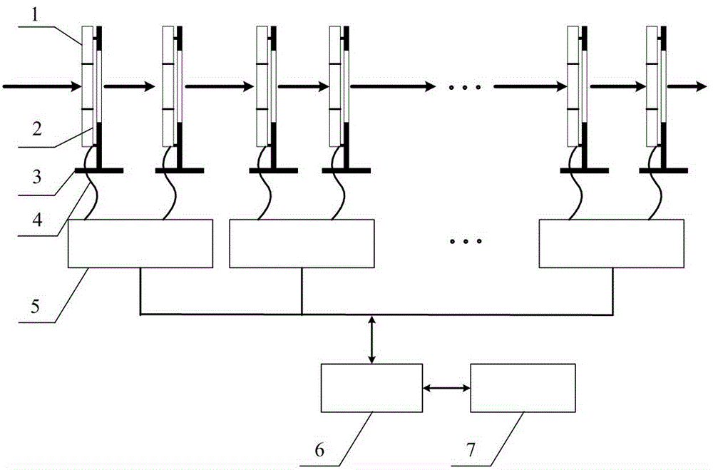
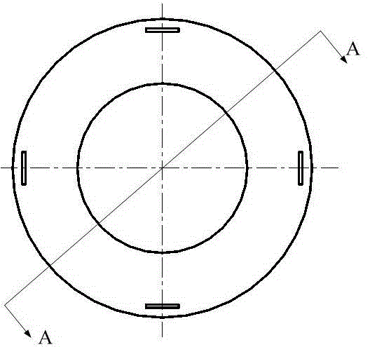
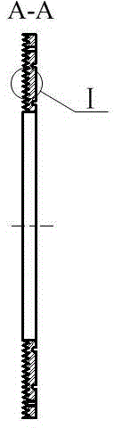
[0022] figure 1 It is a schematic structural diagram of a high-energy laser beam stray light energy measurement system of the present invention, and Fig. 2 (a) is a schematic structural diagram of an absorption aperture in the present invention, (b) is a schematic cross-sectional view of the absorption aperture AA, and (c) is an absorption light Partial enlarged view of appendix I, image 3 It is a schematic diagram of the installation layout of the thermocouple temperature sensor in the present invention, Figure 4 It is a schematic diagram of series connection of thermocouple temperature sensors in the present invention. exist Figure 1 ~ Figure 4 Among them, the high-energy laser beam stray light energy measurement system of the present invention includes several absorption apertures, thermocouple temperature sensors 2, aperture fixing brackets 3, lead wires 4, temperature acquisition modules 5, network switches 6, and host computers 7; The absorption diaphragm 1 is circ...

Embodiment 2

[0031] The structure of embodiment 2 is basically the same as that of embodiment 1. The difference is that the inner diameter of the absorption diaphragm in this embodiment is 1.1 times the outer diameter of the measured laser beam, and the ring-shaped V-shaped groove clip set on the light-facing surface of the absorption diaphragm The angle α is 45°. Sixty-four thermocouple temperature sensors with the same structure are bonded to each absorption aperture. The thermocouple temperature sensors are divided into four groups, and the sixteen thermocouple temperature sensors in each group are correspondingly bonded to the The thermocouple temperature sensor fixing slot located on a concentric circle on the backlight surface of the absorption diaphragm is made of red copper as the material of the absorption diaphragm.

Embodiment 3

[0033] Embodiment 3 has basically the same structure as Embodiment 1. The difference is that in this embodiment, the included angle α of the ring-shaped V-shaped groove arranged on the light-facing surface of the absorption diaphragm is 60°, and each absorption diaphragm is bonded with four Ten thermocouple temperature sensors with the same structure, the thermocouple temperature sensors are divided into five groups, and the eight thermocouple temperature sensors in each group correspond to the thermocouple temperature sensors bonded on a concentric circle on the backlight surface of the absorption aperture. slot.


PUM


Abstract

The invention provides a high energy laser beam stray light energy measuring system which comprises multiple absorption diaphragms, thermocouple temperature sensors, diaphragm fixing supports, leading wires, temperature acquisition modules, a network switch and an upper computer. Each absorption diaphragm has an annular structure which is made of hard aluminum or red copper. A light-facing surface of each absorption diaphragm is provided with an annular V-shaped groove, and the surface is an aluminum oxide and titanium oxide mixture coating layer. The thermocouple temperature sensors are adhered in thermocouple temperature sensor fixing grooves arranged on backlight surfaces of the absorption diaphragms. The thermocouple temperature sensors are connected in series and electrically connected with the temperature acquisition modules via the leading wires. A distribution type measuring system is formed by the temperature acquisition modules, the network switch and the upper computer via network cables. High energy laser beam stray light wide-range and complex distribution dynamic measurement can be effectively realized by the system. Besides, measurement precision is obviously enhanced, and the system has extensibility and transportability with standardized module design.

Description

technical field [0001] The invention belongs to the field of high-energy laser energy measurement, and in particular relates to a high-energy laser beam stray light energy measurement system, which is suitable for ring-shaped high-energy laser beam stray light energy measurement. Background technique [0002] In the process of high-energy laser transmission, the existence of high-frequency component stray light such as laser beam diffraction, high-order modes, and optical component scattering in the channel is an important factor that causes the reduction of laser transmission efficiency and causes partial energy loss. The energy loss caused by stray light will have a major impact on the beam transmission. The energy loss will lead to the overall temperature rise of the channel, which will cause serious wavefront distortion and beam drift in the beam transmission of the inner channel. The temperature rise will lead to structural deformation of the inner channel and the mirro...

Claims


Application Information

Patent Timeline
Patent Type & Authority Applications(China)
IPC IPC(8): G01J1/00G01K7/04
Inventor 范国滨张卫常艳魏继锋周山周文超彭勇田英华黄德权沙子杰蒋志雄胡晓阳
Owner INST OF APPLIED ELECTRONICS CHINA ACAD OF ENG PHYSICS
Why Eureka
Try Eureka