
Surface modified anode material for lithium ion battery and method

A technology for lithium-ion batteries and positive electrode materials, applied in battery electrodes, secondary batteries, chemical instruments and methods, etc., can solve the problems affecting the high-current charge and discharge performance of positive electrode materials, and achieve the goal of overcoming the reduction of high-current charge and discharge performance, The effect of easy control and simple coating process

Inactive Publication Date: 2014-03-12
SHANGHAI INST OF MICROSYSTEM & INFORMATION TECH CHINESE ACAD OF SCI
View PDF4 Cites 32 Cited by
  • Summary
  • Abstract
  • Description
  • Claims
  • Application Information

AI Technical Summary

Problems solved by technology

The existing surface modification method is usually to coat a layer of metal compound on the surface of the positive electrode material, such as Al 2 o 3 , MgO, ZrO 2 、Co 3 (PO 4 ) 2 , AlPO 4 and AlF 3 etc. Although the cycle performance and thermal stability of the positive electrode material can be effectively improved, the low electronic conductivity of the coating layer itself will affect the high-current charge and discharge performance of the coated positive electrode material.

Method used


Image

  • Surface modified anode material for lithium ion battery and method
  • Surface modified anode material for lithium ion battery and method
  • Surface modified anode material for lithium ion battery and method

Examples


Embodiment 1

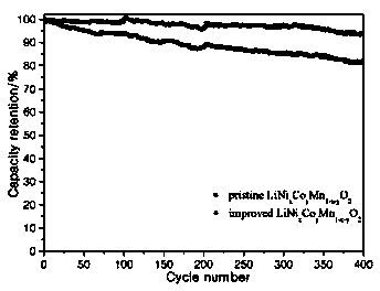
[0020] Example 1: Dissolve 4g of aluminum isopropoxide in 400mL of isopropanol, add 2.7g of citric acid and 100g of LiNi under stirring 1 / 3 co 1 / 3 mn 1 / 3 o 2 , continue to stir the reaction for 4h to fully hydrolyze the aluminum isopropoxide and adjust the pH value to form a sol to adsorb to LiNi 1 / 3 co 1 / 3 mn 1 / 3 o 2 particle surface. Then the temperature was raised to 80°C, evaporated to dryness under stirring, and then the material was placed in a sintering furnace and kept at 300°C for 5 hours at a heating rate of 5°C / min. After cooling in the furnace, 1wt% alumina and 1wt% carbon composite coated LiNi 1 / 3 co 1 / 3 mn 1 / 3 o 2 Material.

Embodiment 2

[0023] Example 2: Dissolve 14.6g magnesium nitrate and 5.0g diammonium hydrogen phosphate in 50mL deionized water, gradually form a magnesium phosphate sol under stirring, then add 2g carbon nanotubes and adjust the pH value to form a sol adsorbed on 100gLiMn 2 o 4 material surface. After continuing to stir for 2 hours, transfer it to a 150°C oven for drying, then treat it at 600°C for 0.5h and sieve to obtain LiMn with 5wt% and 2wt% coatings of magnesium phosphate and carbon nanotubes, respectively. 2 o 4 Material.

Embodiment 3

[0024] Example 3: LiCoO 2 Disperse in a mixed solvent of ethanol and deionized water, where the volume ratio of ethanol and water is 1:1. Then add superconducting carbon black and polyvinylpyrrolidone under stirring, then add an aqueous solution of ammonium fluoride dropwise, react for 1 hour, dry at 100°C, and then heat treat at 500°C for 3 hours to obtain a composite coating of lanthanum fluoride and carbon LiCoO 2 Material. All the other are with embodiment 1.


PUM


Abstract

The invention provides a surface modified anode material for a lithium ion battery and a method. The anode material and the method are characterized in that: LiNi[x]Co[y]MzO2 (M = Mn, Al or Mg), LiMn2O4 or a composite anode material thereof, a metal salt and a carbon source material are added into a solvent to form a flowable slurry; and the pH value is adjusted under stirring so that metal compounds and the carbon source material form sol and are adsorbed on the surface of the anode material. After being dried, the mixture is subjected to high-temperature thermal treatment to obtain the anode material compositely coated with the metal compounds and the carbon, wherein the metal compounds are metal oxides, metal fluorides or metal phosphates, and the like. That large-current charge and discharge performances of anode materials are influenced by the low electronic conductivity of metal compound coatings at present can be overcome by the coating method provided by the invention, thus enhancing application performances in electric tools, electric automobiles, and other occasions.

Description

technical field [0001] The invention relates to a surface-modified anode material and method for a lithium ion battery, in particular to a metal compound and carbon composite coating modified anode material and method for a lithium ion battery. Background technique [0002] Due to the advantages of high energy density, high power density, long cycle life, no pollution, and low self-discharge rate, lithium-ion batteries have already occupied the market of portable electronic products, and have good development potential in the fields of electric tools and electric vehicles. [0003] The core of the lithium-ion battery is the positive and negative electrode lithium storage active materials, in which the positive electrode active material is used as Li in the lithium-ion battery. + The source of battery is the basis of battery energy density, and it is also an important factor restricting the improvement of battery performance. In lithium-ion batteries, during charging and ope...

Claims


Application Information

Patent Timeline
Patent Type & Authority Applications(China)
IPC IPC(8): H01M4/505H01M4/525H01M4/131H01M4/1391
CPCY02E60/122C01G45/12C01G53/44H01M4/505H01M4/525H01M10/0525Y02E60/10
Inventor 张建夏保佳谢晓华娄豫皖
Owner SHANGHAI INST OF MICROSYSTEM & INFORMATION TECH CHINESE ACAD OF SCI
Learn More