
Waste tire recycling method and device

A waste tire and recycling device technology, applied in the field of recycling, can solve problems such as frequent maintenance, secondary pollution, and complicated processing process, and achieve the effects of reducing downtime for maintenance, saving processing costs, and simplifying the processing process

Active Publication Date: 2014-03-26
SHENZHEN INST OF ADVANCED TECH
View PDF5 Cites 31 Cited by
  • Summary
  • Abstract
  • Description
  • Claims
  • Application Information

AI Technical Summary

Problems solved by technology

[0003] At present, there are generally the following methods for processing waste tires: retreading, burning, thermal splitting, and recycling of rubber powder; among them, recycling of rubber powder is widely valued by people. After magnetic and wind sorting, iron filings and fibers are removed to obtain colloidal particles. This method is time-consuming, energy-intensive, noisy, and has secondary pollution.
[0004] At present, the main recycling methods of waste tires include: production of reclaimed rubber, production of rubber powder, heat utilization, pyrolysis, etc. The above-mentioned processes mainly have the following disadvantages when recycling waste tires: complex processing process, high energy and low efficiency, secondary pollution, and frequent maintenance
[0005] At present, some people propose to use low-temperature pulse power generation to crush waste tires, that is, first freeze the waste tires through liquid nitrogen, and then use the liquid electric explosion effect to make the frozen waste tires into rubber particles; the disadvantage of this method is that liquid nitrogen is expensive, and not easy to recycle
[0006] It is also proposed to use supercritical water to oxidize waste tires, that is, under the supercritical state and subcritical state of water, hydrogen peroxide is used as an oxidant to treat waste tires to obtain fuel oil and solid carbon black; The difference is that to maintain the supercritical state of water, the temperature Tc=374.3°C and the pressure Pc=22.05MPa are required, which is not convenient for actual production

Method used


Image

  • Waste tire recycling method and device
  • Waste tire recycling method and device
  • Waste tire recycling method and device

Examples


Embodiment Construction

[0032] In order to make the object, technical solution and advantages of the present invention clearer, the present invention will be further described in detail below in conjunction with the accompanying drawings and embodiments. It should be understood that the specific embodiments described here are only used to explain the present invention, not to limit the present invention.

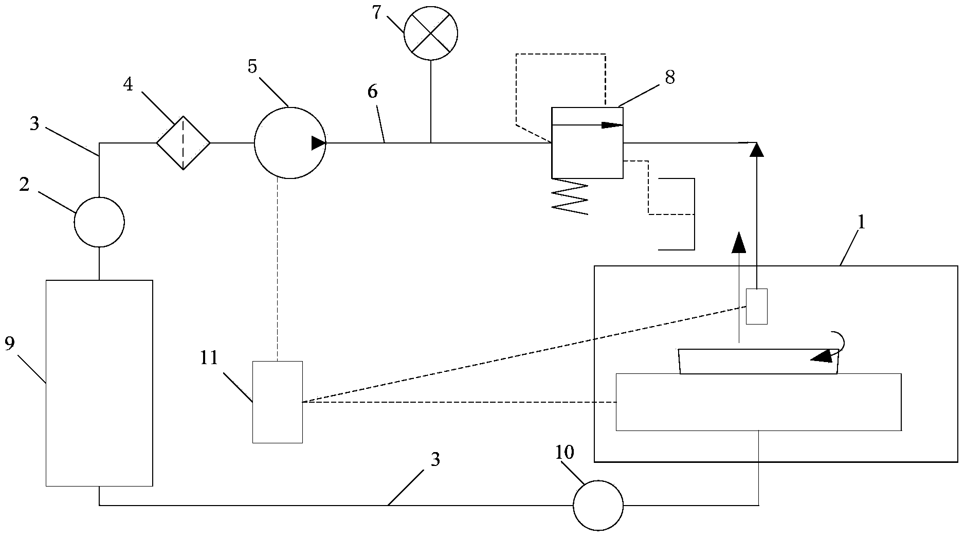
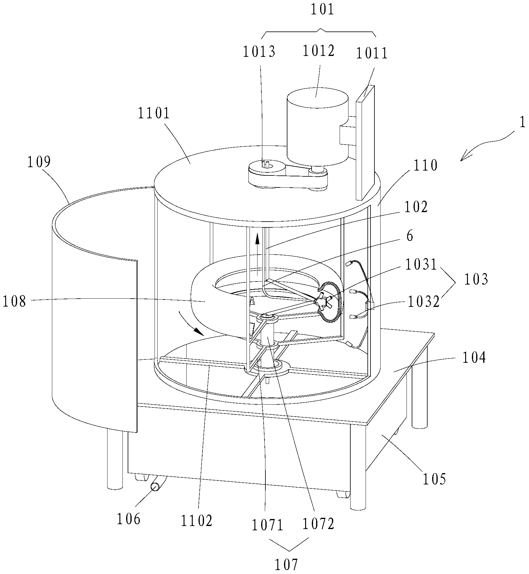
[0033] The present invention firstly provides a method, which is to soak and clean the waste tires, then place them on the workbench, and rotate them at a low speed under the drive of the driving device; It has at least two nozzles that can be connected to high-pressure water jets and are rotatable. When the nozzles are in the working position corresponding to the waste tires to be recycled, start the high-pressure water pump to make high-pressure water jets from each nozzle to form a high-pressure water jet. The surface of the recovered waste tires is subjected to impact cutting, so that the waste...


PUM


Abstract

The invention provides a waste tire recycling method and device. The method comprises the following steps: placing a waste tire to be recycled on a workbench; driving the waste tire to rotate at a low speed with a driving device; arranging rotatable sprayers at the radial periphery of the waste tire, wherein at least two nozzles into which high-pressure water jets can be connected are arranged on each sprayer; starting a high-pressure water pump when all the nozzles are aligned with corresponding working positions of the waste tire, wherein water flows sprayed from the nozzles form high pressure water jet cutters to impact and cut the surface of the waste tire, and decompose the surface of the waste tire layer by layer, peeled rubber granules flow into recovery tanks with sprayed liquid, and wires and fiber are recycled in a centralized manner after being peeled off. As the high pressure water jet treatment technology is used for recycling the waste tire, the treatment process can be simplified, the production efficiency is improved, the energy consumption can be reduced effectively, the whole treatment environment is dust-free and smoke-free, and waste water of treatment can be recycled after filtering; meanwhile, as water jets serve as a non-contact tool, the problem of mechanical knife abrasion is solved, the halting time for maintenance can be shortened, and the treatment cost is reduced.

Description

technical field [0001] The technical field of recycling of the present invention specifically relates to a method for recycling waste tires and a device designed using the method. Background technique [0002] Tires are rubber products, which are difficult to degrade under natural conditions. The accumulation of waste rubber occupies land, pollutes the environment, affects the health of residents and is easy to cause fires. Therefore, the disposal of waste rubber products has become a practical problem to be solved urgently by the environmental protection industry and the rubber industry in various countries. Moreover, my country is the world's largest rubber consumer and the world's largest rubber importer. In 2013, my country's tire output was 490 million, and it showed a trend of year-by-year growth. At present, my country has become the second largest rubber manufacturer after the United States. Scrap tire producing countries. Therefore, how to efficiently and environme...

Claims


Application Information

Patent Timeline
IPC IPC(8): B29B17/00
CPCB29B17/0412B29B2017/0428B29L2030/00Y02W30/62
Inventor 何凯李赳华王焰新毛贺
Owner SHENZHEN INST OF ADVANCED TECH
Learn More