
High-power pulse plasma reinforced composite magnetron sputtering deposition device and application method thereof

A high-power pulsed, magnetron sputtering technology, applied in sputtering, ion implantation, metal material coating, etc. Control the problems of slow sputtering deposition rate and insufficient bonding strength of the coating, so as to improve the ionization rate and the adhesion of the film base, improve the coating efficiency and ion plating effect, and improve the hardness and compactness.

Active Publication Date: 2014-03-26
GUANGDONG UNIV OF TECH
View PDF4 Cites 35 Cited by
  • Summary
  • Abstract
  • Description
  • Claims
  • Application Information

AI Technical Summary

Problems solved by technology

However, there are still some problems in the application of high-power pulse magnetron sputtering technology to deposit hard coatings for high-speed cutting tools: (1) The deposition rate of high-power pulse magnetron sputtering is relatively slow, about 20 times lower than that of ordinary magnetron sputtering. -30%, the efficiency of industrially produced tool coating deposition equipment is too low; (2) Due to the particularity of high-power pulse sputtering plasma discharge, it is not suitable for sputtering of many alloys or compounds like ordinary magnetron sputtering Materials; (3) At present, magnetron sputtering equipment is multi-faceted to molds and various mechanical parts. For heavy-duty coatings such as high-speed cutting tools, the coating deposition temperature and pre-plating bombardment cleaning are not enough, so the coating bonding strength is insufficient.

Method used


Image

  • High-power pulse plasma reinforced composite magnetron sputtering deposition device and application method thereof
  • High-power pulse plasma reinforced composite magnetron sputtering deposition device and application method thereof

Examples


Embodiment Construction

[0024] The technical solutions of the present invention will be further described below in conjunction with the accompanying drawings and through specific implementation methods.

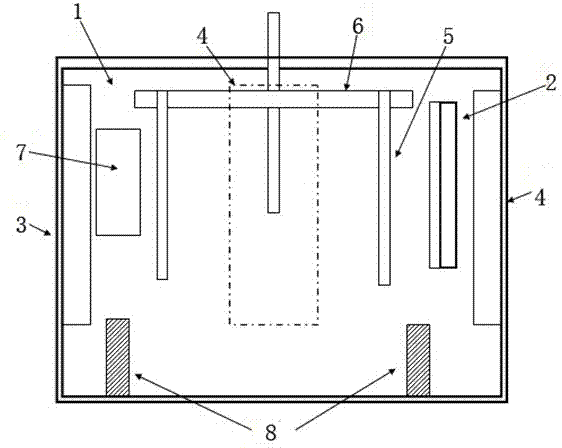
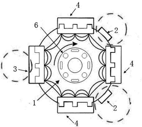
[0025] Such as figure 1 , figure 2 As shown, a high-power pulsed plasma enhanced composite magnetron sputtering deposition device includes a vacuum chamber 1, a magnetron target, a workpiece holder 5 and a rotating support 6;

[0026] The vacuum chamber 1 is a sealed structure, and an air extraction port 7 is opened on it, and the air extraction port 7 is connected with a vacuum pump;

[0027] Such as figure 2 As shown, the magnetron target includes a high-power pulsed magnetron sputtering target 3 and three pulsed DC magnetron targets 4, which are fixed in the vacuum chamber 1 and arranged opposite to each other at 90 degrees, and the layout of the magnetic field is opposite. , forming a closed field; the magnetic field layout of each magnetron target is an unbalanced magnetic field;

[0028]...


PUM


Abstract

The invention relates to the technical field of thin-film materials and particularly relates to a high-power pulse plasma reinforced composite magnetron sputtering deposition device. The device comprises a vacuum chamber, magnetic control targets, a work rest and a rotary support, wherein the magnetic control targets comprise a high-power pulse magnetron sputtering target and pulse direct-current magnetic control targets, fixed in the vacuum chamber, and are arranged in opposite direction in a right angle, the magnetic field arrangement manners of all magnetic control targets are opposite, and a closed field is formed; the magnetic fields of all magnetic control targets are unbalanced magnetic fields; through the implementation of the structure, the better magnetic field distribution and ion plating effects are achieved, high-quality coating with good coating binding force, compact coating, good mechanical performance, accurate and controllable chemical components can be deposited conveniently and the device is applied to high-speed cutting tools.

Description

technical field [0001] The invention relates to the technical field of thin film materials, in particular to a high-power pulsed plasma-enhanced composite magnetron sputtering deposition device and its application method. Background technique [0002] With the development of modern manufacturing industry, the high-speed and high-efficiency cutting of difficult-to-machine materials has put forward higher and higher requirements for tool materials. Coated cutting tools are coated with several microns of high hardness, high wear resistance nitride, oxide or boride coating on the surface of high-strength cemented carbide or high-speed steel (HSS) substrate by vapor deposition method, so that it has High surface hardness, good wear resistance, stable chemical properties, heat resistance and oxidation resistance, small friction coefficient and low thermal conductivity, etc. When cutting, it can increase the tool life by more than 3~5 times compared with uncoated tools, and increas...

Claims


Application Information

Patent Timeline
IPC IPC(8): C23C14/35
Inventor 王启民王成勇伍尚华邹长伟
Owner GUANGDONG UNIV OF TECH
Learn More