
Thermochromic film material and preparation method thereof

A thin-film material and thermochromic technology, which is applied in metal material coating process, vacuum evaporation coating, coating, etc., can solve the problems that cannot meet the requirements of tiny spacecraft, the range of emissivity changes is small, and it is far below room temperature. , to achieve the effect of light weight, large change range and high change temperature range

Active Publication Date: 2014-03-26
NANJING UNIV OF SCI & TECH
View PDF2 Cites 4 Cited by
  • Summary
  • Abstract
  • Description
  • Claims
  • Application Information

AI Technical Summary

Problems solved by technology

Comparative literature 1 (Wua C H, Qiu J W, Wang J B, et al.Thermochromic property of La 0.8 Sr 0.2 MnO 3 thin-film material sputtered on quartz glass.J Alloy Compd,2010,506:22—24) La prepared by magnetron sputtering 0.8 Sr 0.2 MnO 3 Thin film, the emissivity changes from 0.53 (180K) to 0.7 (293K), an increase of 0.17, the range of emissivity change is small, and its Curie temperature is 190K~240K, which is much lower than room temperature; comparative literature 2 (Jiang X, Soltani M ,Mishkinis D,et al.Development of La1-XSrXMnO3Thermochromic Ccating for Smart Spacecraft Thermal Radiator Application,In:Proc.of the10 th ISMSE & the8 th ICPMSE Collioure, France ESA SP-616, 19-23 September 2006) prepared La by pulsed laser deposition 1-x Sr x MnO 3 Thin film, the emissivity changes from 0.49 (218K) to 0.6 (376K), an increase of 0.11, the range of emissivity variation is too small to meet the thermal control requirements of tiny spacecraft

Method used


Image

  • Thermochromic film material and preparation method thereof
  • Thermochromic film material and preparation method thereof

Examples


Embodiment 1

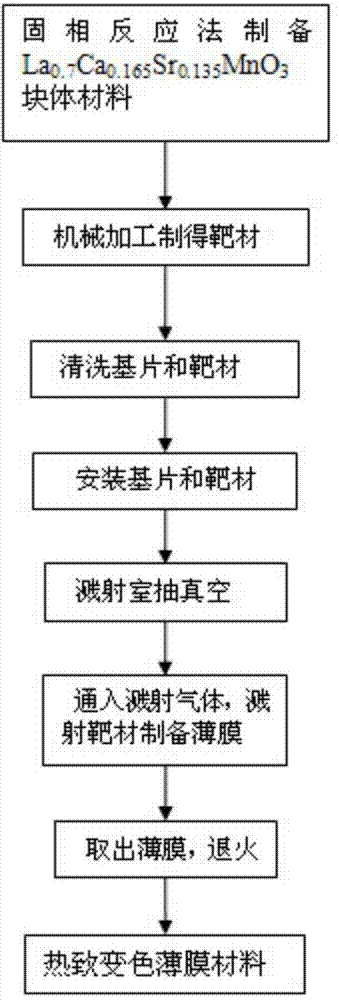
[0018] Such as figure 1 , the film material of the present invention is prepared according to the following steps:

[0019] La 0.7 Ca 0.165 Sr 0.135 MnO 3 Preparation of film samples

[0020] 1. Preparation of La by solid phase reaction method 0.7 Ca 0.165 Sr 0.135 MnO 3 Thermochromic bulk materials (Li Qiang, Kuang Liu, Xuan Yimin. Preparation and radiation characteristics of thermochromic materials with variable emissivity. Journal of Engineering Thermophysics, 2009,30(6):1006—1008), specific process high purity La 2 o 3 , SrCO 3 and MnO 2 The powder is stoichiometrically proportioned, mixed evenly, and then subjected to repeated grinding and high-temperature calcination (1000°C), the calcined powder is ground evenly, and then a binder is added to it and mixed evenly, and then the evenly mixed powder is introduced into the mold and pressed The sheet is shaped and sintered again at high temperature to form a block (1400°C). The bulk material is then machined to ...

Embodiment 2

[0033] La 0.7 Ca 0.165 Sr 0.135 MnO 3 Preparation of film samples

[0034] Steps 1 to 4 are the same as in Example 1

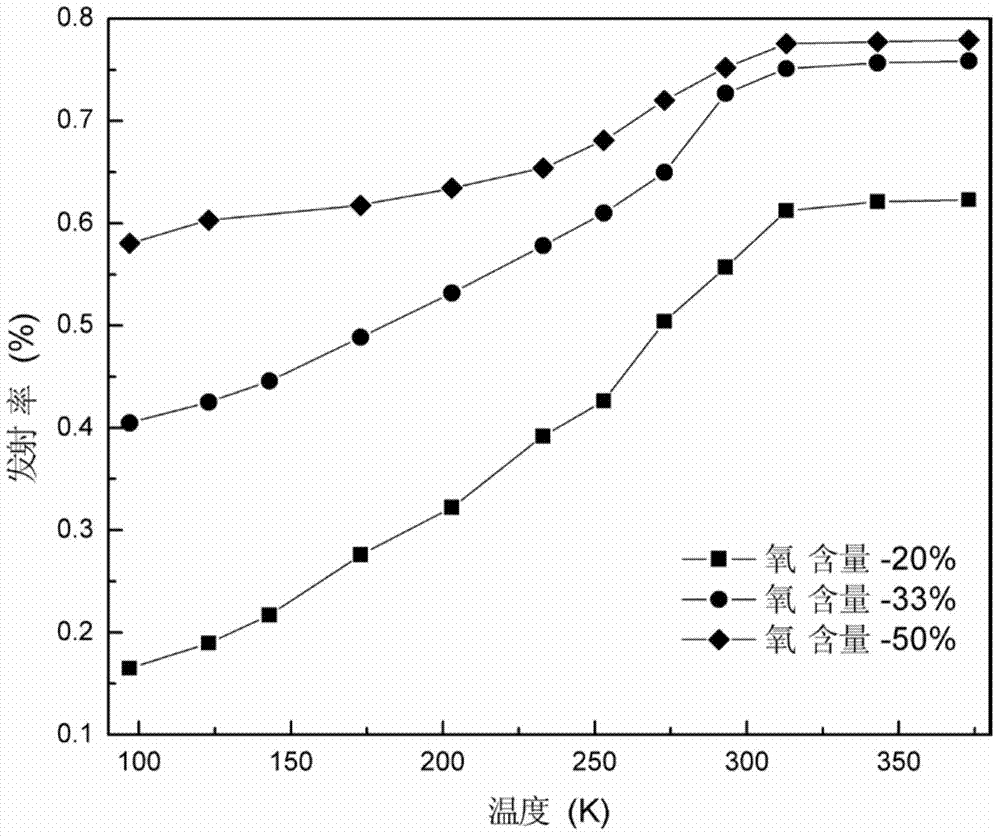
[0035] 5. Fill the sputtering chamber with a mixed gas of argon and oxygen, adjust the air pressure between 0.8Pa, adjust the oxygen partial pressure at 33v%, and prepare La by radio frequency sputtering 0.7 Ca 0.165 Sr 0.135 MnO 3 Thin film, sputtering power at 90W;

[0036] 6. After the sputtering is over, wait for the sputtering chamber to cool down, open the vent valve, expose the sputtering chamber to the atmosphere, and take out the film sample;

[0037] 7. Anneal the film sample in an oxygen flow of 1 atmosphere. The heating temperature curve is heated from room temperature to 400°C at a heating rate of 3°C / min, and then heated to 700°C at a heating rate of 1°C / min, and kept for 2 hours. , then cooled to 400°C at a rate of 1°C / min, and finally cooled to room temperature at a rate of 3°C / min to obtain the product

Embodiment 3

[0039] La0.7 Ca 0.165 Sr 0.135 MnO 3 Preparation of film samples

[0040] Steps 1 to 4 are the same as in Example 1

[0041] 5. Fill the sputtering chamber with a mixed gas of argon and oxygen, adjust the air pressure between 0.8Pa, adjust the oxygen partial pressure at 50v%, and prepare La by radio frequency sputtering 0.7 Ca 0.165 Sr 0.135 MnO 3 Thin film, sputtering power at 90W;

[0042] 6. After the sputtering is over, wait for the sputtering chamber to cool down, open the vent valve, expose the sputtering chamber to the atmosphere, and take out the film sample;

[0043] 7. Anneal the film sample in an oxygen flow of 1 atmosphere. The heating temperature curve is heated from room temperature to 400°C at a heating rate of 3°C / min, then heated to 700°C at a heating rate of 1°C / min, and kept for 2 hours. , followed by cooling down to 400°C at a rate of 1°C / min, and finally cooling down to room temperature at a rate of 3°C / min to obtain the product.

[0044] The La p...


PUM

PropertyMeasurementUnit
emissivityaaaaaaaaaa

Abstract

The invention discloses a thermochromic film material and a preparation method of the thermochromic film material. The film material is La0.7Ca0.165Sr0.135MnO3. The preparation method comprises the following steps of preparing an La0.7Ca0.165Sr0.135MnO3 block material by adopting a solid-phase reaction method, and then machining the block material to prepare a target material; cleaning a substrate and the target material; installing the target material and the substrate, injecting the mixed gas of argon gas and oxygen gas into a sputtering chamber, adjusting the gas pressure to be 0.8Pa, adjusting the content of the oxygen gas to be 20 to 50v%, and preparing an La0.7Ca0.165Sr0.135MnO3 thermochromic film by adopting radio-frequency magnetron sputtering; annealing a film sample in an oxygen-gas flow under 1 atmospheric pressure at the annealing temperature of 700 DEG C for 2 hours to obtain a product after natural cooling. The thermochromic film disclosed by the invention has the advantages of small size, light weight, high reliability and the like, and compared with a thermochromic block material, the requirement of spacecrafts on device lightweight can be better met; the emissivity of the thermochromic film material can be conveniently measured; the emissivity-changing range of the material is large, the temperature-changing interval is high, and the material has larger changes at the temperature close to a room temperature; the thermochromic film material can be used for the outer-surface radiation control of microsatellites.

Description

technical field [0001] The invention relates to a thermochromic thin film material and a preparation method thereof, belonging to the field of thin film material preparation. Background technique [0002] With the increasing development of aerospace technology, micro-miniature spacecraft, due to their small size, light weight, and small thermal inertia, must integrate a large number of high-performance, compact, and miniaturized electronic components in a small area, resulting in heat flow A sharp increase in density. At the same time, micro-spacecraft have requirements for wide-range orbital mobility, multiple working modes, weight reduction, energy consumption and cost reduction, which makes it difficult for traditional mechanical shutters and other thermal control devices to meet the thermal requirements of micro-spacecraft due to their heavy mass and large volume. control requirements. [0003] Perovskite manganese oxide is a thermochromic variable emissivity material,...

Claims


Application Information

Patent Timeline
Patent Type & Authority Applications(China)
IPC IPC(8): C23C14/35C23C14/08C23C14/58
Inventor 宣益民李强戴平范德松
Owner NANJING UNIV OF SCI & TECH
Learn More