Comprehensive testing method of optical performance of deep ultraviolet optical element

A technology of deep ultraviolet and comprehensive testing, which is applied in the direction of testing optical properties, etc., can solve the problems of simultaneous and in-situ measurement of fluorescence spectrum, and the inability to simultaneously measure the change of H2 content in deep ultraviolet optical components, so as to save costs Effect

Inactive Publication Date: 2014-04-09
INST OF OPTICS & ELECTRONICS - CHINESE ACAD OF SCI
View PDF6 Cites 14 Cited by
  • Summary
  • Abstract
  • Description
  • Claims
  • Application Information

AI Technical Summary

Problems solved by technology

Chinese patent application "A comprehensive test method for the stability of deep ultraviolet optical components" (patent application number 201010623885.2, application publication date 2010.09.07) proposes a comprehensive test integrating laser calorimetry technology, photothermal technology and laser-induced fluorescence spectroscopy technology The technology comprehensively measures the stability of deep ultraviolet optical elements. Although it can simultaneously determine the real-time changes of the absorption characteristics and fluorescence spectral characteristics of deep ultraviolet optical elements under deep ultraviolet laser irra

Method used


Image

  • Comprehensive testing method of optical performance of deep ultraviolet optical element
  • Comprehensive testing method of optical performance of deep ultraviolet optical element
  • Comprehensive testing method of optical performance of deep ultraviolet optical element

Examples


Embodiment Construction

[0026] The present invention will be further described below in conjunction with the accompanying drawings and specific embodiments.

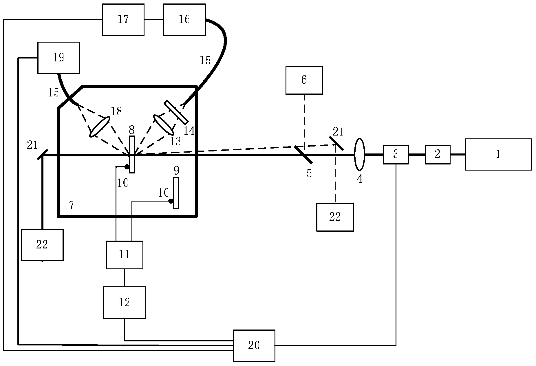
[0027] Such as figure 1 As shown, the present invention uses a coupling optical fiber to couple and transmit a comprehensive test device for Raman scattered light, which consists of a narrow linewidth deep ultraviolet laser light source 1, a beam shaping system 2, an electronically controlled variable optical attenuator 3, a focusing lens 4, and an electric optical shutter 5 , laser power meter 6, adiabatic sample chamber 7, tested sample fixture and tested deep ultraviolet optical element sample 8, reference sample fixture and reference sample 9, sensitive temperature detection unit 10, bridge amplifier circuit 11, A / D converter 12. Fluorescence collection optical system 13, narrow-band optical filter 14, coupling optical fiber 15, monochromator 16, fluorescence photodetection device 17, Raman scattered light collection optical system 18, high...


PUM


Abstract

The invention provides a comprehensive testing method of the optical performance of a deep ultraviolet optical element. According to the comprehensive testing method, the absorption loss absolute value of the deep ultraviolet optical element is measured based on the laser heat measurement technology; the fluorescence spectrum of the deep ultraviolet optical element is measured based on the laser-induced fluorescence spectrum technology when the deep ultraviolet optical element is irradiated by a deep ultraviolet laser; the defect level, the contents of doping components and the content of impurities of a material of the deep ultraviolet optical element are measured based on the Raman spectra technology. Through measurement of the absorption loss feature, the fluorescence spectrum feature and the Raman spectral feature of the deep ultraviolet optical element at the deep ultraviolet laser wavelength, the comprehensive optical performance of the deep ultraviolet optical element is estimated. By measuring the real-time change of the absorption loss, the fluorescence spectrum and the Raman spectrum of the deep ultraviolet optical element in the process of deep ultraviolet laser irradiation, the stability of the performance of the deep ultraviolet optical element is monitored. By the adoption of the same device, the optical feature parameters of the deep ultraviolet optical element are measured and the change of the optical feature of the deep ultraviolet optical element in the process of deep ultraviolet laser irradiation is monitored in real time.

Description

technical field [0001] The invention relates to a method and device for measuring parameters of an optical element, in particular to a comprehensive test method for the optical performance of a deep ultraviolet optical element, which can test the optical performance and stability of the deep ultraviolet optical element. Background technique [0002] In VLSI manufacturing process, excimer laser lithography is one of the most important processes. At present, the main laser light source used in semiconductor integrated circuit lithography equipment is argon fluoride (ArF) excimer laser with an output wavelength of 193nm. In lithography equipment, deep ultraviolet optical elements are widely used, including reflective optical elements, transmission optical elements, attenuation optical elements, etc., for shaping, transmission and control of 193nm laser beams. The optical materials used to prepare these deep ultraviolet optical components are mainly ultraviolet-grade fused sili...

Claims


Application Information

Patent Timeline
IPC IPC(8): G01M11/02
Inventor 李斌成
Owner INST OF OPTICS & ELECTRONICS - CHINESE ACAD OF SCI
Why Eureka
Try Eureka