
Arc metal stud welding method and device under friction cleaning and homogenization

A welding method and stud technology, applied in arc welding equipment, welding equipment, non-electric welding equipment, etc., can solve the problems of reducing the welding performance of the workpiece, large heat-affected zone, necking, etc., and achieve improved welding quality and large diameter span , Improve the effect of temperature field

Active Publication Date: 2016-01-20
江苏靖宁智能制造有限公司
View PDF11 Cites 2 Cited by
  • Summary
  • Abstract
  • Description
  • Claims
  • Application Information

AI Technical Summary

Problems solved by technology

Among them: induction and arc composite heat source stud welding can use induction heating device to coordinate pre-weld preheating, welding, and post-weld annealing to reduce the degree of restraint and prevent cold cracks, but the welding interface is easy to generate a large area The intermetallic compound, the joint toughness is not enough, and it is also prone to defects such as necking, flash, poor fusion, welding deviation, etc., just like arc stud welding.
Induction and friction combined heat source stud welding is a welding method that uses induction heating to heat the workpiece to reduce the required frictional heat generation. However, due to the large area of ​​induction heating and the large heat-affected zone, the welding performance of the workpiece is reduced
Friction and friction composite heat source is a method that uses the outer ring for friction preheating and the inner ring for stud friction welding. This method solves the problem of single friction stud welding system when welding studs while retaining the advantages of solid phase welded joints. The problem of insufficient heat production, but the device is complex and the utilization rate of heat source is low
Resistance and friction composite heat source is a method that uses resistance heat and friction heat to heat joints to achieve welding. Although this method can reduce friction pressure and spindle power, it cannot solve the problem of large diameter studs and thick workpieces. welding
[0004] European Patent Office EP1595635A1 discloses an arc stud welding method. Although the method is simple to implement and can solve the welding problem of small-diameter metal studs with tapered corners, the single arc heat source is heated and the arc heating range is limited. For flat-head studs The arc starting point is not easy to control, and hollow studs cannot start arcs. Therefore, for large-diameter or flat-headed metal studs, the ends are heated unevenly, and the stud root is prone to defects such as poor fusion, so this method cannot solve medium and large diameters or flat-headed or hollow studs. Welding requirements for metal studs and thick metal plates; and for the welding of brittle dissimilar materials, brittle phases such as intermetallic compounds are prone to occur, which seriously affects the quality of the joints, so the welding problem of brittle dissimilar materials cannot be solved
The arc stud welding method produces melting between the stud end surface and the plate surface, and cannot completely extrude the molten metal. If dissimilar materials form brittle intermetallic compounds, it is easy to crack, and it is difficult to realize dissimilar materials such as aluminum studs-steel plates. stud welding
[0005] U.S. Patent US2006086707A1 discloses a method of arc compound friction stir welding, which can only realize the butt welding of plates and plates, but cannot realize the joint form of stud welding; and the arc heat source and friction heat source used are independent heat sources, and the arc only It can be placed before or after the stirring head, and the welding area cannot be heated at the same time, so it is not suitable for stud welding that requires the heat source used to heat the stud end and the corresponding plate position; this method is mainly based on frictional heat source, and the stirring head is only a heating tool , is the friction of the third body, the stirring head itself does not participate in the connection, and is not a part of the joint, while the stud in stud welding participates in the connection, which is actually body friction, so the principle of friction stir welding and stud welding is different, friction stir welding Cannot be applied to the welding of the stud end face and the plate
[0006] Chinese patent 200710092974.7 discloses a conduction-friction stir composite heat source welding method and equipment. Although this method can expand the scope of application of friction stir welding to the welding of structural materials such as ferrous metals and superalloys, it can only achieve welding of butt joints , the joint form of stud welding cannot be realized; this method is mainly based on friction heat source, the stirring head is only a heating tool, which is the third body friction, the stirring head itself does not participate in the connection, it is not a part of the joint, and the stud in stud welding Participating in the connection is body friction, so the principles of friction stir welding and stud welding are different. Friction stir welding cannot be applied to stud welding, let alone welding of large-diameter, brittle and difficult-to-weld conductive metal studs
In this method, if the resistance heating is too strong, the strength of the stirring head will decrease, which will cause damage to the stirring head. Therefore, resistance heating can only be used as a supplementary and auxiliary heat source. studs in column welding

Method used


Image

  • Arc metal stud welding method and device under friction cleaning and homogenization
  • Arc metal stud welding method and device under friction cleaning and homogenization
  • Arc metal stud welding method and device under friction cleaning and homogenization

Examples


Embodiment 1

[0031] Example 1, taking the welded 30CrNi3MoV solid metal stud with a diameter of 6mm and a length of 80mm and the finished welded joint of 30CrNi3MoV with a plate thickness of 3mm as an example, the shielding gas is CO 2 , air flow 17L / min:

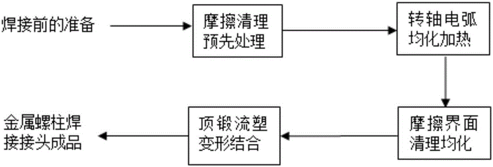
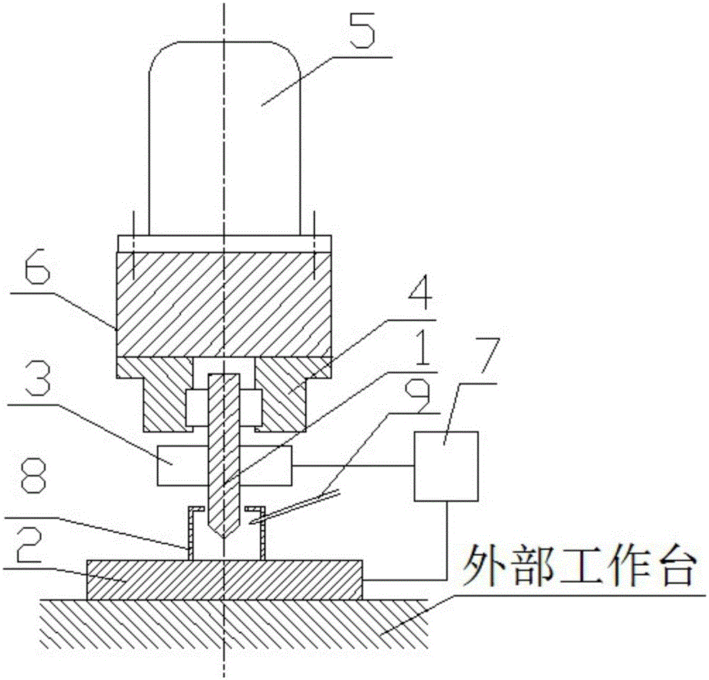
[0032] Step 1, friction cleaning pre-treatment: start the metal stud axial displacement device (6) and the motor (5), and the metal stud (1) rotates at 3000r / min, so that the metal stud (1) is on the metal stud shaft Under the joint action of the displacement device (6) and the motor (5), it moves along the axial direction and contacts the surface of the metal substrate (2), and at the same time applies a pressure of 5MPa, so that the end surface of the metal stud (1) is in contact with the surface of the metal substrate (2). Direct friction occurs on the surface. After 1 second of friction, remove impurities such as oxides and oil stains on the surface of the metal stud (1) and the metal substrate (2), and at the same time make the end...

Embodiment 2

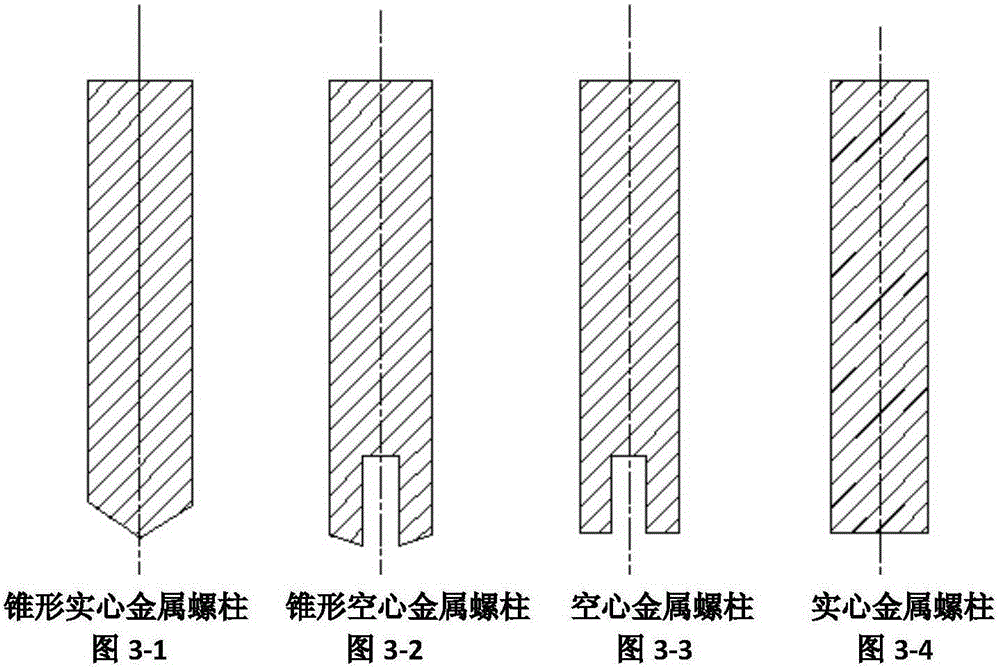
[0036] Example 2, taking a 30CrNi3MoV conical metal stud with a diameter of 20mm and a length of 80mm as an example, and a finished welded joint of a 6061 aluminum alloy with a plate thickness of 40mm as an example, the shielding gas is Ar, and the gas flow rate is 16L / min:

[0037] Step 1, pre-treatment of friction cleaning: start the metal stud axial displacement device (6) and the motor (5), the speed of the metal stud (1) is 2000r / min, so that the metal stud (1) is on the metal stud shaft Under the joint action of the displacement device (6) and the motor (5), it moves along the axial direction and contacts the surface of the metal substrate (2), and at the same time applies a pressure of 18MPa, so that the end surface of the metal stud (1) is in contact with the surface of the metal substrate (2). Direct friction occurs on the surface. After 2 seconds of friction, remove impurities such as oxides and oil stains on the surface of the metal stud (1) and the metal substrate (...

Embodiment 3

[0041] Embodiment 3, taking the welded joint finished product of 6061 aluminum alloy hollow metal stud with a welding diameter of 30mm, inner hole diameter of 12mm, and a length of 80mm, and a 6061 aluminum alloy with a plate thickness of 80mm as an example, the shielding gas is Ar, and the gas flow rate is 18L / min:

[0042] Step 1, pre-treatment of friction cleaning: start the metal stud axial displacement device (6) and the motor (5), the speed of the metal stud (1) is 300r / min, so that the metal stud (1) is on the metal stud shaft Under the joint action of the displacement device (6) and the motor (5), it moves along the axial direction and contacts the surface of the metal substrate (2), and at the same time applies a pressure of 30MPa, so that the end surface of the metal stud (1) is in contact with the surface of the metal substrate (2). Direct friction occurs on the surface. After 3 seconds of friction, remove impurities such as oxides and oil stains on the surface of ...


PUM

PropertyMeasurementUnit
diameteraaaaaaaaaa

Abstract

The invention relates to an electrical arc metal stud welding method and an electrical arc metal stud welding device under frictional cleaning homogenization. According to the electrical arc metal stud welding method and the electrical arc metal stud welding device under the frictional cleaning homogenization, a worker preprocesses the end face of a metal stud and the surface of a metal base plate through frictional cleaning, heats a spindle dynamic arc in homogenization mode, and combines cleaning homogenization and upset forging plastic flow deformation of a friction interface together, and accordingly a metal stud welding joint end product which is excellent in performance is obtained. The electrical arc metal stud welding method and the electrical arc metal stud welding device under the frictional cleaning homogenization can achieve welding of thick and large metal sheets and large diameter metal studs, are suitable for welding between a steel, nickel, copper, titanium, aluminum, or magnesium metal stud and a base plate made of metal material as same as or different from the metal stud, and are particularly suitable for welding of metal studs made of fragile conductor material which is difficult to weld and metal studs made of high carbon equivalent steel.

Description

technical field [0001] The invention relates to a metal stud welding method, in particular to an arc metal stud welding method and device under friction cleaning and homogenization. Background technique [0002] Metal stud welding refers to a method of welding metal studs or similar metal columns and other fasteners to metal workpieces. As a simple, high-speed, low-consumption, and low-pollution advanced welding technology, metal stud welding is widely used in the fields of vehicles, shipbuilding, boilers, steel structures, construction, electronics, instruments, and medical equipment. According to the classification of the heat source for realizing metal stud welding, metal stud welding can be divided into welding methods such as resistance welding, friction welding, explosive welding and arc welding. According to the classification of power sources for metal stud welding, arc stud welding can be divided into stable arc stud welding (arc stud welding), unstable arc stud we...

Claims


Application Information

Patent Timeline
Patent Type & Authority Patents(China)
IPC IPC(8): B23K28/02B23K9/20B23K20/12
CPCB23K9/16B23K9/20B23K9/235B23K28/02
Inventor 周琦王克鸿张德库朱军张惠芸彭勇
Owner 江苏靖宁智能制造有限公司
Learn More