BOG (Boil Off Gas)-zero emission LNG (Liquefied Natural Gas) storage method and device

A storage device and zero-emission technology, which is applied in the field of LNG storage without BOG (flash steam), can solve the problems of high equipment investment costs and large floor space, and achieve small floor space, low cost, and high condensation efficiency. Effect

Active Publication Date: 2014-04-30
广东广大新能源科技有限公司
View PDF6 Cites 11 Cited by
  • Summary
  • Abstract
  • Description
  • Claims
  • Application Information

AI Technical Summary

Problems solved by technology

Fundamentally solve the problems of high equipment investment costs and large floor space caused by rec

Method used


Image

  • BOG (Boil Off Gas)-zero emission LNG (Liquefied Natural Gas) storage method and device
  • BOG (Boil Off Gas)-zero emission LNG (Liquefied Natural Gas) storage method and device
  • BOG (Boil Off Gas)-zero emission LNG (Liquefied Natural Gas) storage method and device

Examples


Embodiment 1

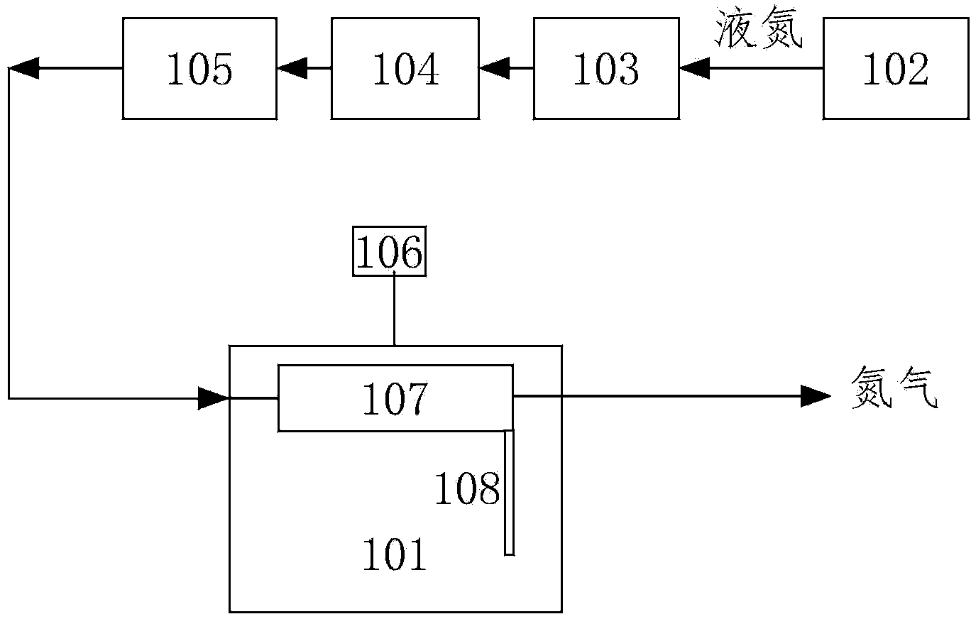
[0030] A BOG zero-emission LNG storage method and device in an LNG receiving station. The parameters of the LNG storage tank are as follows: the capacity is 160,000 m3, the maximum design pressure is 29kpa, the diameters of the outer tank and the inner tank are 82000mm and 80000mm respectively, and the temperature inside the tank is ‐162°C, the total amount of LNG is 7680t, the daily evaporation rate is 0.05%, and the working pressure value of the BOG condenser is specified as 15-20kpa.

[0031] Determination of liquid nitrogen flow rate: -162°C BOG production q B It is 7680×0.05%=3.84t / d, which is 0.16t / h. The chemical process simulation software Aspen is used for simulation calculations, and the required liquid nitrogen flow rate q is calculated according to the fact that BOG is condensed at -162°C to a saturated liquid at -162°C, and liquid nitrogen is vaporized from -196°C to -170°C N , the result q N =0.365t / h, then the ratio of recovered BOG mass to consumed liquid nit...

Embodiment 2

[0041] A BOG zero-discharge LNG storage method and device in an LNG satellite station. The parameters of the LNG storage tank are as follows: the capacity is 350 cubic meters, the maximum design pressure is 10Mpa, the diameters of the outer tank and inner tank are 4500mm and 4000mm respectively, and the temperature in the tank- 140°C, the total amount of LNG is 477t, the daily evaporation rate is 0.1%, and the working pressure value of the BOG condenser is specified as 6Mpa.

[0042] Determination of liquid nitrogen flow rate: -140°C BOG production q B It is 477×0.1%=0.477t / d, which is 19.8kg / h. The chemical process simulation software Aspen is used for simulation calculations, and the required liquid nitrogen flow rate q is calculated according to the fact that BOG is condensed at -140°C to a saturated liquid at -140°C, and liquid nitrogen is vaporized from -196°C to -170°C N , the result q N =40kg / h, then the ratio of recovered BOG mass to consumed liquid nitrogen mass, q ...


PUM

PropertyMeasurementUnit
Thicknessaaaaaaaaaa

Abstract

The invention discloses BOG (Boil Off Gas)-zero emission LNG (Liquefied Natural Gas) storage method and device. The BOG-zero emission LNG storage device is characterized in that one end of a flow guide pipe is connected to a BOG condenser, and the other end of the flow guide pipe is immersed in liquid phase of an LNG storage tank; the BOG condenser is arranged in a gas phase space of the upper part of the LNG storage tank; an LNG storage tank pressure detector is arranged in the gas phase space of the upper part of the LNG storage tank; a condenser pipe comprises a hollow pipe, a helical fin and an axial flow guide plate, liquid nitrogen is in pipe pass, and the outer part of the pipe is filled with BOG; the helical fin is arranged on the periphery of the hollow pipe, and the axial guide plate is arranged at the right lower end of the hollow pipe; the hollow pipe is slantwise arranged from an inlet end to an outlet end, and the slant angle theta between the hollow pipe and the horizontal plane is 10 degrees to 30 degrees. The BOG (Boil Off Gas)-zero emission LNG (Liquefied Natural Gas) storage method and device realize the effective integration of LNG storage and BOG recovery and the zero emission of BOG while realizing the effective storage of LNG, has strong applicability and is easy to control.

Description

technical field [0001] The invention relates to the technical field of LNG (liquefied natural gas) storage, in particular to a BOG (flash steam)-free LNG storage method and device. Background technique [0002] The storage temperature of LNG is -162°C, and the storage equipment is a low-temperature and atmospheric pressure storage tank. The gas formed by the evaporation of light components in LNG is BOG, and BOG gathers above the storage tank to form a gas phase space. The reasons for the formation of BOG due to the evaporation of LNG are as follows: Since the temperature difference between LNG and the outside world can reach more than 200°C, the heat from the outside world continuously passes through the inner and outer walls of the storage tank to the inside of the storage tank; when the submerged pump in the LNG tank is running, part of the mechanical energy is converted It is heat energy; volume displacement generated when LNG ships or trucks are unloading; atmospheric p...

Claims


Application Information

Patent Timeline
IPC IPC(8): F17C1/00F17C13/02F17C13/00F17C13/04
Inventor 徐文东赵建河郑境森
Owner 广东广大新能源科技有限公司
Why Eureka
Try Eureka