Microbubble generator and preparation method thereof

A micro-bubble generator and carbon nanotube technology, applied in the field of micro-electromechanical systems, can solve the problems of easy corrosion and high power consumption, and achieve the effects of not easy electrolysis or corrosion, prolonging life, and improving frequency response.

Active Publication Date: 2015-12-09
HUAZHONG UNIV OF SCI & TECH
View PDF4 Cites 3 Cited by
  • Summary
  • Abstract
  • Description
  • Claims
  • Application Information

AI Technical Summary

Problems solved by technology

[0004] Aiming at the above defects or improvement needs of the prior art, the present invention provides a microbubble generator and a preparation method thereof, which use carbon nanotubes as heating components and graphene as electrode materials to overcome the traditional metal electrode microbubble generators. The shortcomings of high power consumption and easy corrosion reduce the contact resistance of the micro-heater, thereby reducing the power consumption of the micro-bubble generator and effectively prolonging the life of the micro-bubble generator. The device has a simple structure, flexible design, and good performance. High-frequency response and dense integration potential have broad application prospects in advanced manufacturing

Method used


Image

  • Microbubble generator and preparation method thereof
  • Microbubble generator and preparation method thereof

Examples


preparation example Construction

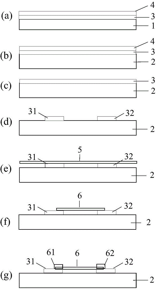
[0025] Such as figure 1 Shown, the preparation method of the microbubble generator of an embodiment of the present invention comprises the steps:

[0026] (1) Spin-coat a layer of polymethyl methacrylate (PMMA) 4 on the surface of metal foil 1 grown with graphene 3, such as figure 1 (a) shown.

[0027] (2) Corrode metal foil 1 with ferric chloride or ammonium persulfate solution to obtain graphene 3 protected by PMMA4. After cleaning with deionized water, transfer it to substrate 2 cleaned by standard CMOS process, heat treatment to make graphite ene 3 is tightly bound to the substrate 2, as figure 1 (b) shown.

[0028] (3) Soak in acetone to remove PMMA4, and obtain graphene 3 transferred to substrate 2, such as figure 1 (c) shown.

[0029] (4) Graphene electrodes 31 and 32 are obtained by photolithography and reactive ion etching, such as figure 1 (d) shown. The distance between the electrodes is 1-8 μm. If the distance is too small, it is easy to cause a short circui...

Embodiment 1

[0045] The preparation method of microbubble generator comprises the steps:

[0046] (1) Spin-coat a layer of PMMA with a thickness of about 200 nm on the surface of copper foil with single-layer graphene growth.

[0047] (2) Etch the metal foil with 0.5mol / L ammonium persulfate solution to obtain PMMA-protected graphene, wash it with deionized water for 3 times, transfer it to the substrate cleaned by the standard CMOS process, and dry it Bake at 150°C for 10 minutes to make the graphene tightly bonded to the substrate.

[0048] (3) Soak in acetone for 1 hour to remove PMMA and obtain graphene transferred to the substrate.

[0049] (4) Two graphene electrodes were obtained by photolithography and oxygen plasma reactive ion etching with an electrode spacing of 1 μm.

[0050] (5) Covering Cu 2 O nanoparticles, with Cu 2 O nanoparticles as catalyst, methane gas as carbon source, using low-pressure CVD process, heating up to 800°C at a rate of 50°C / s, and growing horizontally...

Embodiment 2

[0054] The preparation method of microbubble generator comprises the steps:

[0055] (1) Spin-coat a layer of PMMA with a thickness of about 200 nm on the surface of copper foil with single-layer graphene growth.

[0056] (2) Etch the metal foil with 0.5mol / L ammonium persulfate solution to obtain PMMA-protected graphene, wash it with deionized water for 4 times, transfer it to the substrate cleaned by the standard CMOS process, and dry it Bake at 150°C for 10 minutes to make the graphene tightly bonded to the substrate.

[0057] (3) Soak in acetone for 1 hour to remove PMMA and obtain graphene transferred to the substrate.

[0058] (4) Two graphene electrodes were obtained by photolithography and oxygen plasma reactive ion etching with an electrode spacing of 8 μm.

[0059] (5) Covering Cu 2 O nanoparticles, with Cu 2 O nanoparticles as a catalyst, methane gas as a carbon source, using a low-pressure CVD process, the temperature was raised to 950°C at a rate of 50°C / s, an...


PUM

PropertyMeasurementUnit
thicknessaaaaaaaaaa
thicknessaaaaaaaaaa
thicknessaaaaaaaaaa

Abstract

The invention discloses a microbubble generator and a preparation method thereof. The microbubble generator comprises a substrate, two electrodes and a carbon nano tube, wherein each of the two electrodes comprises graphene; the carbon nano tube is connected with the two electrodes through the graphene and is used as a heating component. The preparation method comprises the following steps of performing spin-coating on the surface of a metal foil, on which the graphene grows, with PMMA (polymethyl methacrylate); removing the metal foil, transferring the graphene protected by the PMMA to the substrate, and performing thermal treatment to enable the graphene to be tightly combined with the substrate; removing the PMMA; performing photoetching and reaction ion etching to obtain the two graphene electrodes; and covering the substrate with Cu2O nano particles serving as a catalyst, and with a hydrocarbon as a carbon source, growing a horizontal orientated carbon nano tube perpendicular to the graphene electrodes under the temperature of 800-950 DEG C through a low-pressure CVD (chemical vapor deposition) technology. The power consumption of the microbubble generator is reduced, and the service life of the microbubble generator is effectively prolonged; furthermore, the microbubble generator is simple in structure and flexible in design and has good high-frequency response and intensive integration potential.

Description

technical field [0001] The invention belongs to the technical field of micro-electromechanical systems, and more specifically relates to a micro-bubble generator and a preparation method thereof. Background technique [0002] The microbubble generator consists of three parts: a substrate, a heating element and an electrode. The huge Joule heat generated by the heating element fixed between the electrodes heats the liquid to generate bubbles. The microbubble generator is not only the core of the thermal bubble thermal printing system, but also can be widely used in the MEMS field and microfluidic system as a bubble actuator, bubble valve and bubble power pump. For example, microbubble generators generate bubbles to drive liquid flow in capillary channels, serve as actuators for microbial mixing systems, and trap microbial particles. [0003] Existing micro-bubble generators all use or partly use metal materials, and the power consumption of the device is relatively high. At ...

Claims


Application Information

Patent Timeline
Patent Type & Authority Patents(China)
IPC IPC(8): B01J19/08
Inventor 周文利邓武竹
Owner HUAZHONG UNIV OF SCI & TECH
Why Eureka
Try Eureka