
Hydrogenation reaction system and method

A technology of hydrogenation reaction and reactor shell, which is applied in the direction of hydrogenation treatment process, chemical instruments and methods, chemical/physical processes, etc., can solve the problems of reducing catalyst reaction space, limiting catalyst expansion ratio, increasing operation difficulty, etc. Achieve the effects of improving operational flexibility and stability, increasing effective volume, and prolonging residence time

Active Publication Date: 2014-05-07
CHNA ENERGY INVESTMENT CORP LTD +1
View PDF9 Cites 20 Cited by
  • Summary
  • Abstract
  • Description
  • Claims
  • Application Information

AI Technical Summary

Problems solved by technology

However, since the reactor is divided into different reaction sections by using partitions, it is necessary to form an effective separation of solids and gas-liquid mixtures in different reaction sections, otherwise the catalyst will block the channels on the distribution plate, which will require increasing the separation space or adding Separate equipment, which limits the catalyst expansion ratio, reduces the catalyst reaction space, and increases the difficulty of operation

Method used


Image

  • Hydrogenation reaction system and method

Examples


Embodiment 1

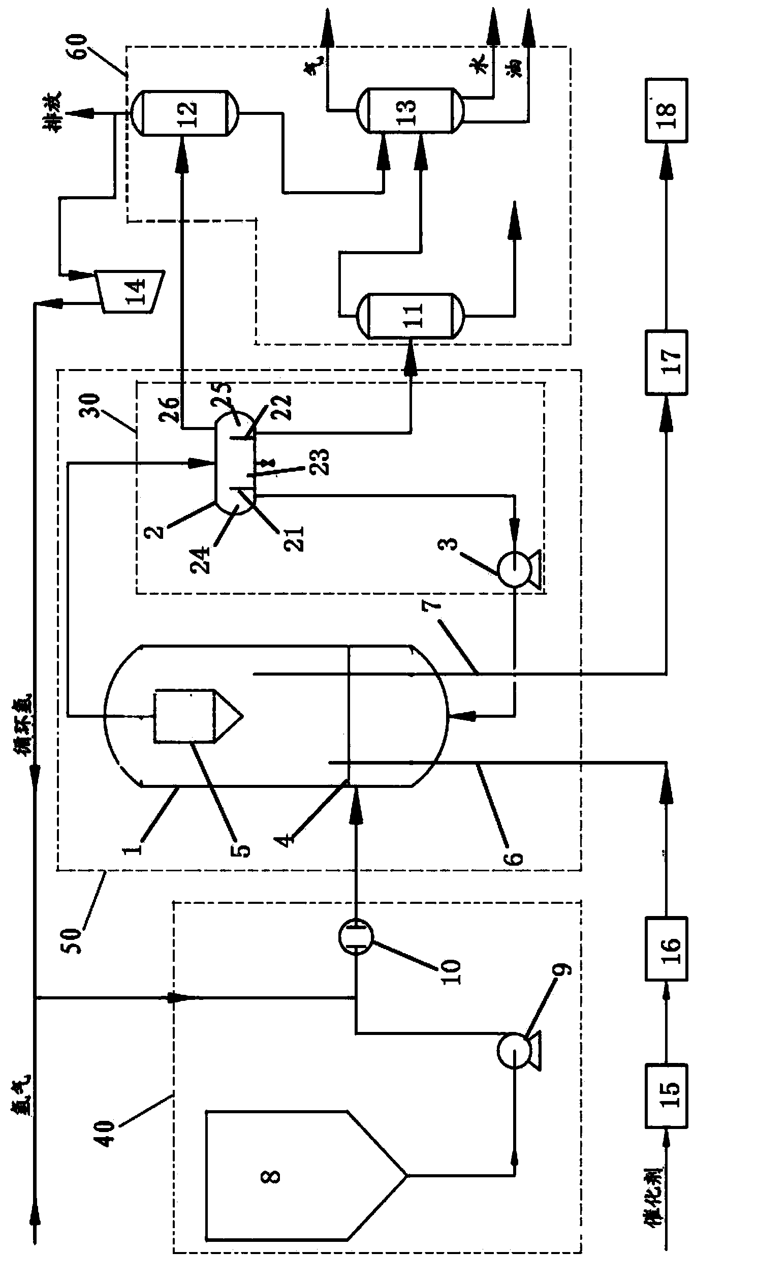
[0054] Coal liquefied oil hydrogenation test is carried out by using the fluidized bed reactor of the present invention. The reactor shell is 35m high, including the middle straight section and the upper and lower elliptical heads. The straight section is 31m high and 4.5m in diameter; 0.1m, the inlet end of the catalyst unloading pipeline is 20m away from the distributor; the structure of the hot high-pressure separator is as follows figure 1 As shown, the diameter (height) is 5m, the first and second baffles are 3m high, the middle part is 5m wide, and the first and second parts are 2m wide.

[0055] The hydrogenation catalyst used in the test is a hydrogenation catalyst with alumina as the carrier, and its manufacturer is Beijing Sanju Environmental Protection New Materials Co., Ltd., and the brand is FFT-1B. Above the distributor in the reactor shell is the effective volume of the reactor, and the filling volume of the catalyst in the reactor is 60% of the effective volum...

Embodiment 2

[0065] The difference from Example 1 is that the outlet end of the catalyst dosing pipeline and the inlet end of the catalyst unloading pipeline are both 0.1 m away from the distributor, and the rest of the reaction conditions are the same. During the test, the amount of unloading and replenishment of the catalyst was 1.2 tons / day. The properties of the product leaving the hot high pressure separator are shown in Table 4.

[0066] Table 4

[0067] Analysis Project

analysis results

Density (20℃), g / cm 3

0.9634

O,m%

0.51

S,μg / g

27.3

N,μg / g

739

Hydrogen supply index, mg-Hnβ / g-solvent

19.26

Distillation range (ASTM D-86), °C

initial boiling point

106

10% / 30%

222 / 275

50% / 70%

305 / 333

90% / FBP

388 / 498

[0068] As can be seen from the experimental results, compared with Example 2, when the ebullating bed reactor in Example 1 is used to carry out the hy...


PUM


Abstract

The invention discloses a hydrogenation reaction system adopting a boiling bed reactor. The hydrogenation reaction system comprises a feeding unit, a boiling bed reactor and a separating unit; the invention also discloses a method for treating direct coal liquefaction effluents by use of the hydrogenation reaction system. The active volume of the reactor is increased, and the operating flexibility and the stability are improved; and besides, a separating device is arranged in a circulating unit of the boiling bed reactor, the content of solid particles in feeding materials of the circulating pump is reduced, the abrasion to the circulating pump is reduced and the service life of the circulating pump is prolonged.

Description

technical field [0001] The invention relates to a hydrogenation reaction system and method, in particular to a hydrogenation reaction system and method for hydrogenation treatment of coal direct liquefied oil by using an ebullated bed reactor. Background technique [0002] The process usually used for catalytic hydrogenation of coal liquefied oil is mainly fixed bed hydrogenation process. Fixed bed reactors are especially suitable for handling lighter and cleaner materials, such as naphtha, middle distillates, etc. The fixed bed reactor is characterized by relatively stable operation and easy control. Because coal liquefied oil is heavy and contains many mechanical impurities, the catalytic reaction conditions will be relatively harsh. At the same time, high-nitrogen raw materials will accelerate the deactivation of the catalyst, shorten the service life of the catalyst, make the product properties unstable, and the pressure drop of the catalyst bed is relatively low. high...

Claims


Application Information

Patent Timeline
IPC IPC(8): C10G67/02B01J8/24
Inventor 舒歌平吴秀章张继明张传江陈茂山刘东明段晓军安亮杨东刘建平刘永贾振斌
Owner CHNA ENERGY INVESTMENT CORP LTD
Learn More