Engine energy-saving carbon-reduction efficiency improving assisting device
An auxiliary device and engine technology, applied in the charging system, adding non-fuel substances to the fuel, electrolysis process, etc., can solve the problems of high pollution components in exhaust gas, easy generation of black smoke, and inability to further reduce fuel consumption, etc., to achieve clean Effects of carbon deposition, horsepower enhancement, and combustion efficiency improvement
- Summary
- Abstract
- Description
- Claims
- Application Information
AI Technical Summary
Problems solved by technology
Method used
Image

Examples
Embodiment Construction
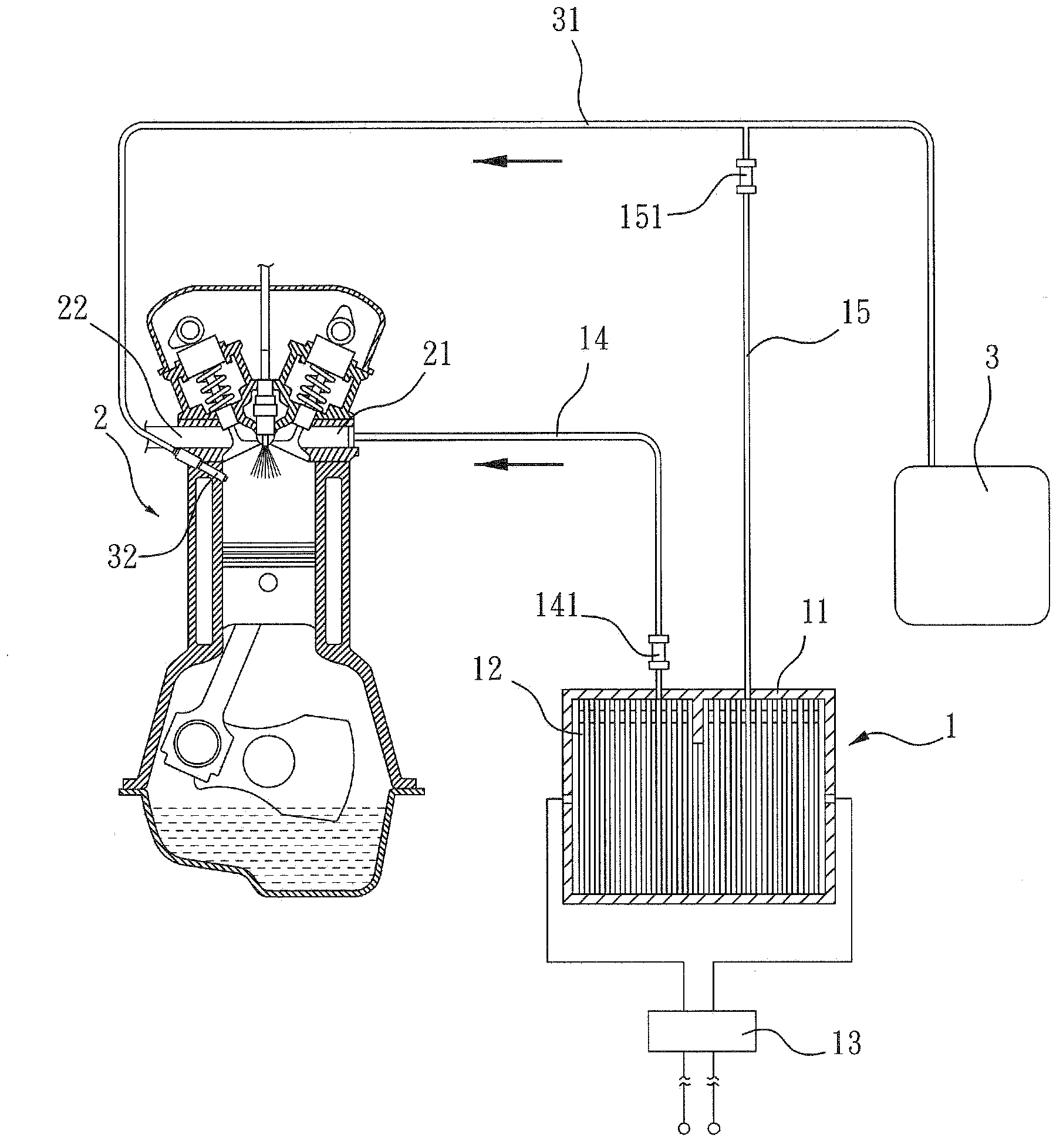
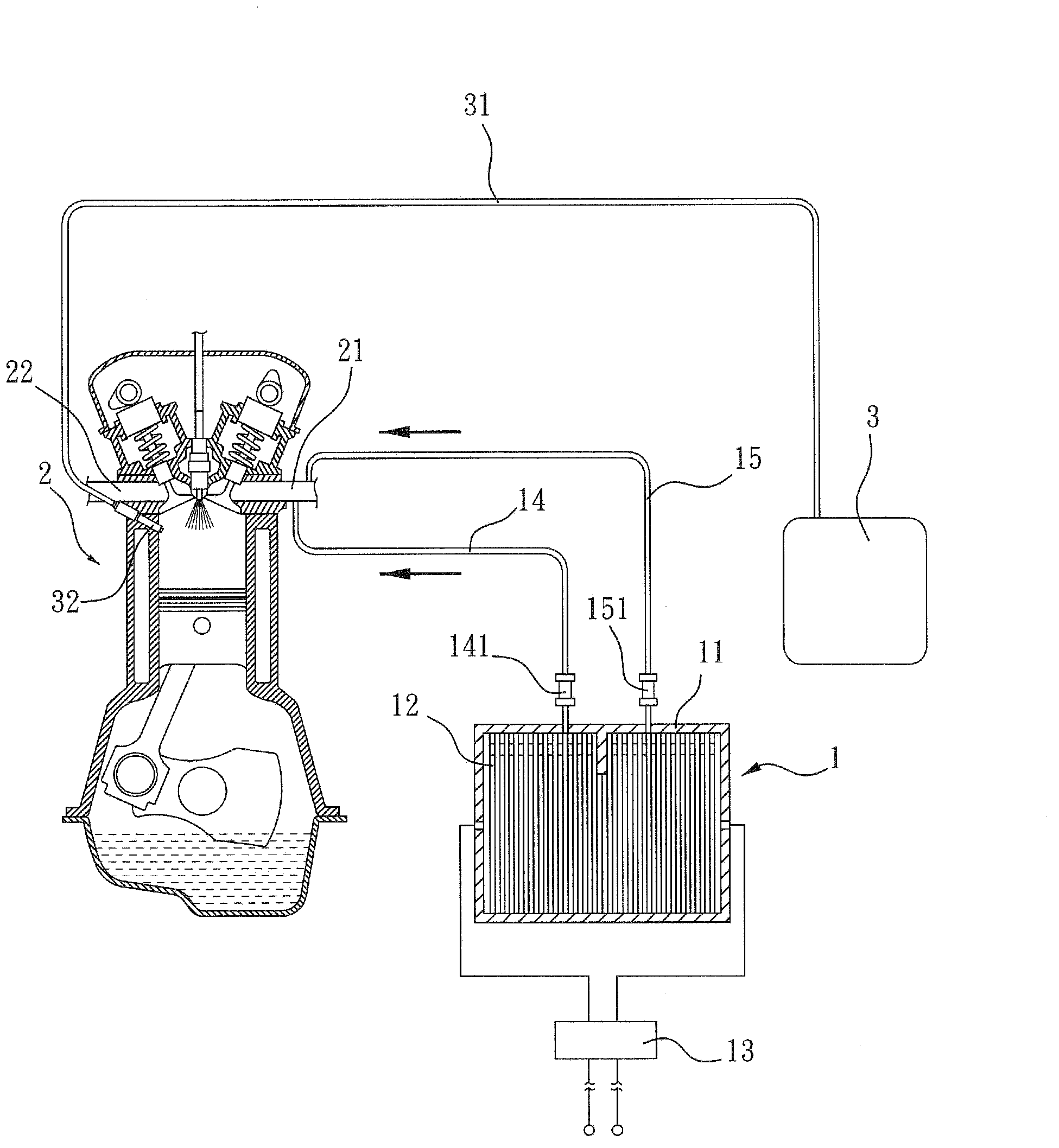
[0022] The specific implementation manners of the present invention will be described in more detail below in conjunction with the drawings, so as to have a further understanding of the technical means, functions and effects of the present invention.
[0023] figure 1 It shows the schematic diagram of the first embodiment of the auxiliary device of the present invention applied to the automobile fuel supply system; it is characterized in that an electrolytic cell 1 is installed in an appropriate position of the automobile, and a plurality of chemical reactions are provided inside the cell body 11 of the electrolytic cell 1 to generate electrolysis plate 12, the electrolytic tank 1 is electrically connected to the battery equipped with the car through a transformer 13; the battery voltage of a general car is 12V (volts), and the voltage is reduced to 6V (volts) through the transformer 13 and then input into the electrolytic tank 1 to provide For electrolytic chemical reactions....
PUM
 Abstract
Description
Claims
Application Information