

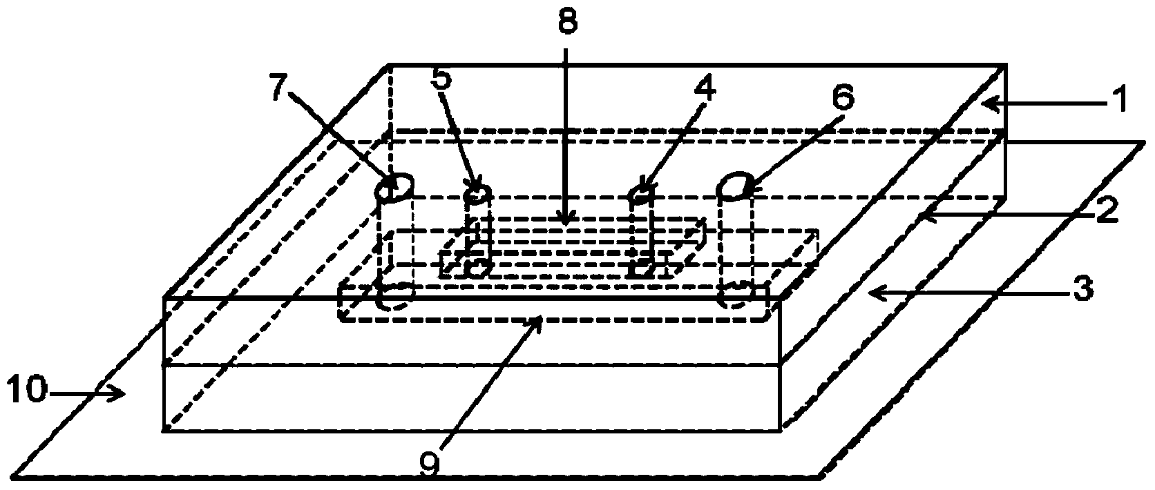
Artery blood vessel simulation microfluid control device enabling direct observation under high-power objective
An arterial vessel simulation and microfluidic device technology, applied in the field of biomedicine, can solve the problem of inability to observe the dynamic changes of cells, and achieve the effects of being easy to manufacture and use, promoting progress, and having a simple structure
- Summary
- Abstract
- Description
- Claims
- Application Information
AI Technical Summary
Problems solved by technology
Method used
Image


Examples
Embodiment 1
[0051] Example 1 Stretch detection of the elastic membrane during the operation of the arterial blood vessel simulation microfluidic device of the present invention
[0052] Add HeLa cells to the microfluidic channel in the arterial simulating microfluidic device of the present invention, and make the cells adhere to the elastic membrane under the conditions of 37°C and 5% carbon dioxide; Observe the cells on the elastic membrane, the results are as follows figure 2 As shown, the stretch rate of the elastic film after negative pressure stretching is about 8% compared with that before stretching.
Embodiment 2
[0053] Example 2 Observation of the fine structure of cells in the arterial vessel simulation microfluidic device of the present invention under a high-magnification objective lens
[0054] Human umbilical vein endothelial cells are added to the microfluidic channel of the arterial vessel simulation microfluidic device of the present invention, and the cells are attached to the elastic membrane under the conditions of 37°C and 5% carbon dioxide; the mechanical conditions of the arterial vessel are simulated for cell culture 2 Hours later, the cells were fixed, and the nuclei and microfilaments were stained. Under the stretched condition of the elastic membrane, the fine structure of the cells on the elastic membrane was observed with a 63-fold lens, and the results were as follows image 3 As shown, the fine structure of cells can be clearly observed.
PUM
 Abstract
Description
Claims
Application Information