Eddy current retarder device based on magnetorheological effect

A technology of eddy current retarder and magneto-rheological effect, which is applied in the fields of electric vehicles, transportation and packaging, and brake types, etc., can solve the problems of difficult excitation device, high manufacturing precision, and complex structure, etc., and can improve the braking torque. controllability, improve low-speed braking performance, and reduce braking response time

Inactive Publication Date: 2014-05-21
FUZHOU UNIV
View PDF8 Cites 11 Cited by
  • Summary
  • Abstract
  • Description
  • Claims
  • Application Information

AI Technical Summary

Problems solved by technology

[0007] 1. The structure of the hydraulic retarder is complicated, the manufacturing precision is high, and the cost is high
[0008] 2. The braking torque of the hydraulic retarder is very small at low speed, which cannot meet the braking requirements; and when braking, it takes a certain time for the working hydraulic pressure to enter the working chamber, resulting in a long braking response time
However, only using the rheological characteristics of magnetorheological fluid under the action of an external magnetic field to generate braking torque for braking, so the braking torque provided is very limited
Chinese patent 201210434149.1, entitled "Independent hydraulic retarder based on magnetorheological fluid and its control method", uses magnetorheological fluid as the working fluid of the hydraulic retarder, and through the rheology of the magnetorheological fluid characteristics to increase the braking torque and improve the low-speed performance of the retarder, but its structure is complex, it is difficult to design an excitation device that makes the viscosity of the magnetorheological fluid change uniformly, and the magnetorheological fluid with uneven viscosity has a flow field in the vortex cavity The complexity is difficult to ensure the stability of the braking effect

Method used


Image

  • Eddy current retarder device based on magnetorheological effect
  • Eddy current retarder device based on magnetorheological effect
  • Eddy current retarder device based on magnetorheological effect

Examples


Embodiment Construction

[0029] In order to make the above-mentioned features and advantages of the present invention more comprehensible, the following specific embodiments are described in detail with reference to the accompanying drawings.

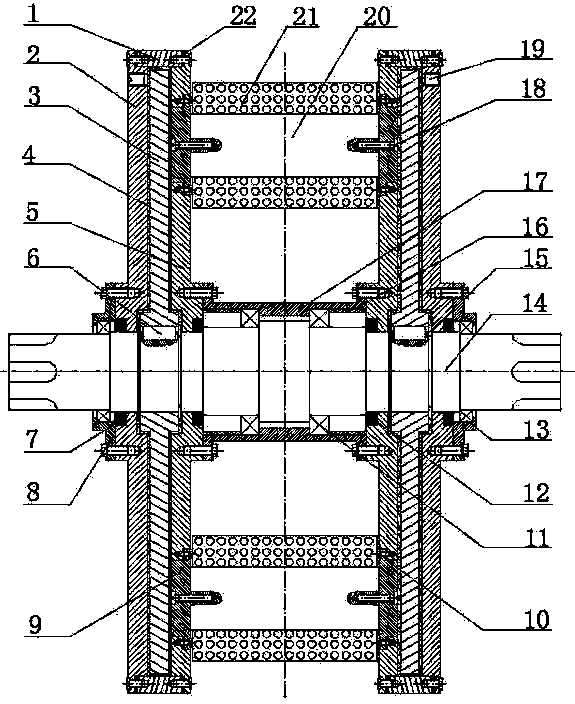
[0030] like figure 1 As shown, the present invention is a symmetrical structure with a central stator assembly and double rotors on both sides, including a cylindrical shell 1 (2 pieces), an outer shell 2 (2 pieces), a rotor disk 3 (2 pieces), a magnetic Rheological fluid 4, inner housing 5 (2 pcs), ordinary flat key 6 (2 pcs), outer lip seal ring 7 (2 pcs), bearing cover 8 (2 pcs), pole shoe 9 (16 pcs), Sector seal ring 10 (4 pcs), inner bearing 11 (2 pcs), inner lip seal ring 12 (2 pcs); outer bearing 13 (2 pcs), drive shaft 14, spring circlip 15 (4 pcs), sleeve Barrel 16 (2 pcs), bearing sleeve 17, countersunk head screw 18 (16 pcs), slotted flat end set screw 19 (4 pcs), magnetic core 20 (8 pcs), excitation coil 21 (8 pcs), seal Washers 22 (4 pcs). Among...


PUM


Abstract

The invention relates to an eddy current retarder device based on the magnetorheological effect. The eddy current retarder device comprises rotor discs, a stator assembly, a transmission shaft and magnetorheological fluid. The stator assembly comprises a bearing sleeve, stator shells and the like and is located in the middle, the two rotor discs are placed in the stator shells on the two sides of the stator assembly respectively, and gaps between the shells and the rotor discs are filled with the magnetorheological fluid. Eight excitation devices are respectively fixed to the inner side shell of the stator shells on the two sides. Through the structure, air gaps between rotors and a stator are replaced by the magnetorheological fluid with high magnetic permeability and low electrical conductivity, and therefore magnetic circuit magnetic resistance is reduced; meanwhile, under the magnetic field effect, the magnetorheological fluid is converted from Newtonian fluid with low viscosity into Bingham fluid with high shear yield stress. In the brake process, the brake torque generated by eddy currents and the brake torque generated by the magnetorheological fluid act at the same time. The eddy current retarder device with the structure has the advantages of being capable of saving energy and electricity, small in coil heating amount, large in brake torque, and good in brake torque controllability and low-speed performance.

Description

technical field [0001] The invention relates to an eddy current retarder based on magnetorheological effect, in particular to an eddy current retarder using magnetorheological fluid as a magnetic conduction medium and a working medium at the same time. Background technique [0002] With the development of the automobile industry, the driving speed of automobiles is getting faster and faster, and the braking performance and safety of automobiles are also widely concerned. In the case of continuous braking for a long time, traditional brakes will produce thermal fading, which will greatly reduce the braking efficiency and seriously affect the safety performance of the car. With the introduction of relevant national automobile safety regulations in recent years, auxiliary brakes must be installed on large trucks and buses. The auxiliary brake of the automobile can bear most of the braking energy, reduce the braking load of the service brake, and greatly improve the safety...

Claims


Application Information

Patent Timeline
Patent Type & Authority Applications(China)
IPC IPC(8): F16D57/02B60L7/28
Inventor 陈淑梅王程郭源帆郑祥盘
Owner FUZHOU UNIV
Why Eureka
Try Eureka