Chromic acid wastewater treatment method and system

A technology for wastewater treatment and chromic acid, which is applied in metallurgical wastewater treatment, water/sewage treatment, water/sewage multi-stage treatment, etc. It can solve the problems of poor adsorption effect of cation exchange resin, low concentration and high transportation cost. The effect of saving equipment investment, simple operation procedures and reducing production costs

Inactive Publication Date: 2014-06-04
黄运富
View PDF5 Cites 11 Cited by
  • Summary
  • Abstract
  • Description
  • Claims
  • Application Information

AI Technical Summary

Problems solved by technology

To treat chromic acid wastewater by chemical reduction, neutralization and precipitation, it is necessary to add precipitant, reducing agent, and condensing agent to chromic acid wastewater. Treating 1 kg of chromic acid will produce 10 kg of sludge, and a large amount of sludge will be generated during the treatment process. The environmental problems caused by sewage discharge are prominent
Although the currently popularized anion and cation resin exchange method emphasizes zero discharge of wastewater recycling, the industry accepts it to a low degree, because the anion resin contains sodium chromate. When the concentration of chromic acid is high, the damage to the resin is great, and a large amount of pure water is required to clean the sodium chromate, and the accumulation of anode metal impurities is large, which makes the adsorption effect of the cation exchange resin worse

Method used


Image

  • Chromic acid wastewater treatment method and system
  • Chromic acid wastewater treatment method and system
  • Chromic acid wastewater treatment method and system

Examples


Embodiment 1

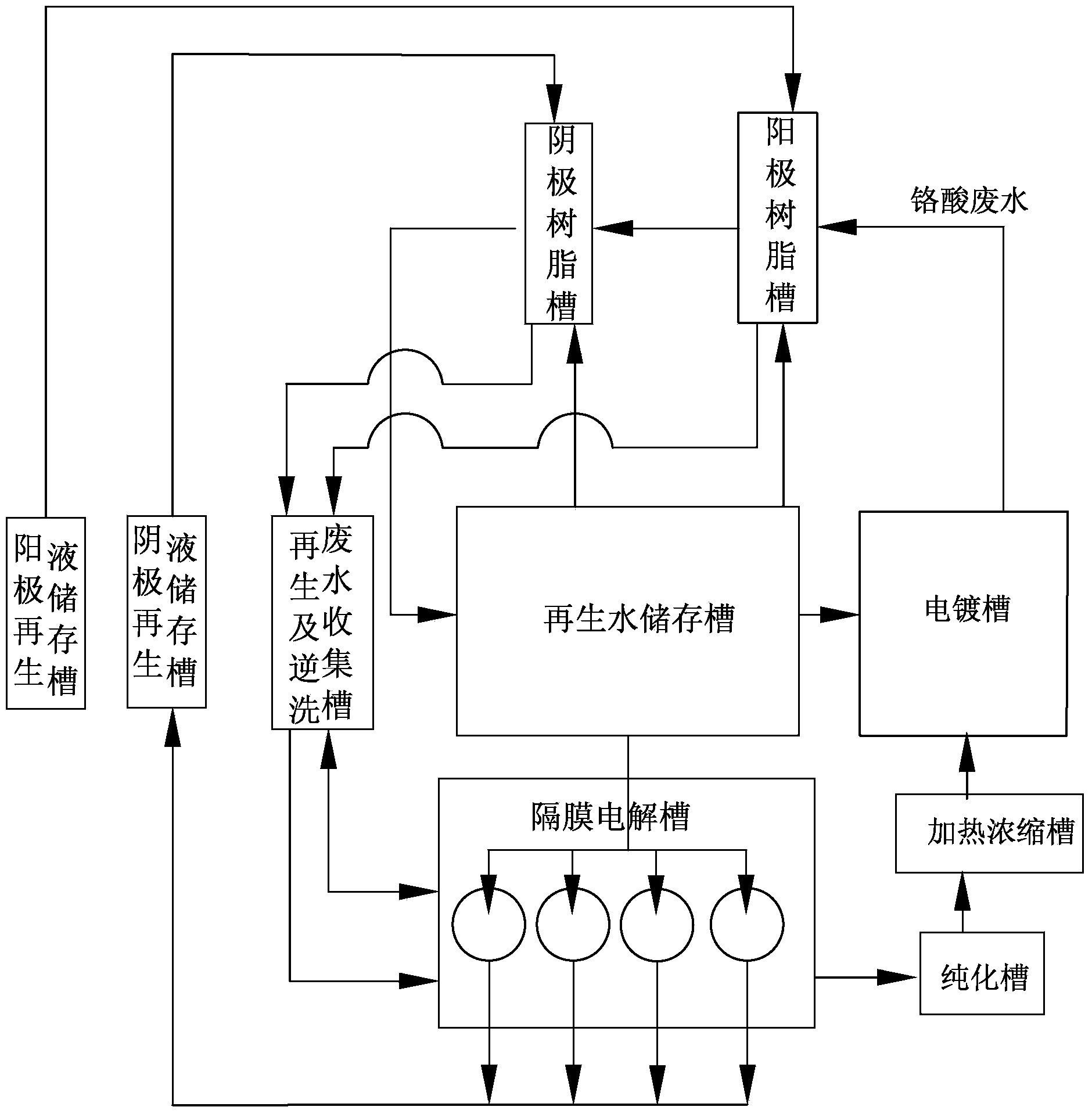
[0086] First, the chromic acid wastewater is injected into the anode resin tank equipped with cation exchange resin for ion exchange, and then the chromic acid wastewater flowing out of the anode resin tank is injected into the anion resin tank equipped with anion exchange resin, and the chromic acid wastewater becomes in line with the discharge standard regenerated water, the regenerated water is input into the regenerated water storage tank for standby; when the exchange capacity of the cation exchange resin through ion exchange is close to or reaches saturation, stop inputting chromic acid waste water to the anode resin tank, and use the cation exchange resin with a concentration of 1 to 4wt% The sulfuric acid solution soaks the cation exchange resin for more than 48 hours. At this time, the sulfuric acid solution becomes the anode regeneration waste liquid. The anode regeneration waste liquid is collected for treatment, and the cation exchange resin is backwashed with regene...

Embodiment 2

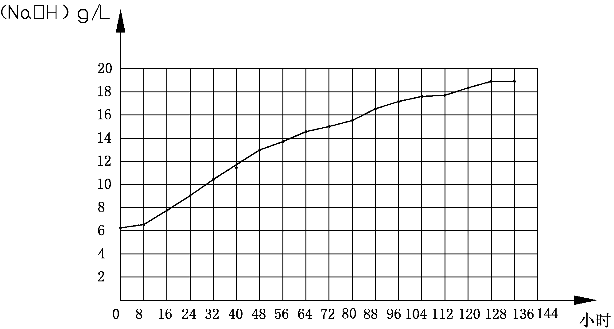
[0092] time h Concentration g / L 0 6.33 8 6.5 16 8 24 9.8 32 11.6 40 12.4 48 15.2 56 16.3 64 17.1 72 18 80 18.3 88 18.5 96 18.9 104 19.1 112 19.3 120 19.3 128 19.3

[0093] Gained cathode sodium hydroxide concentration graph sees figure 1 .

[0094] At the beginning of electrolysis, the current was very small because the temperature was low. As the time of electrolysis increased, the temperature continued to rise. At the beginning, the concentration of sodium hydroxide in the ceramic cylinder was only 1%, but after 16 hours, the current increased rapidly. The concentration of sodium hydroxide also increased sharply, but the current dropped significantly after 72 hours, and the increase rate of the concentration of sodium hydroxide also slowed down. After 96 hours, the current almost dropped to zero, and the bubbles produced by the cathode plate were also very small, which means ...

Embodiment 3

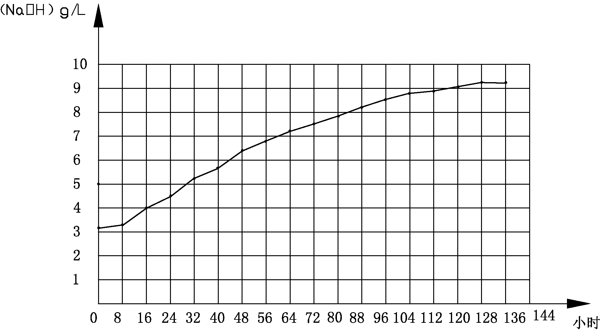
[0096] time h Concentration g / L 0 3.1 8 3.2 16 3.9 24 4.5 32 5.2 40 5.7 48 6.4 56 6.8 64 7.2 72 7.5 80 7.8 88 8.2 96 8.6 104 8.8

[0097] 112 8.9 120 9.1 128 9.3 136 9.3

[0098] Gained cathode sodium hydroxide concentration graph sees figure 2 .

[0099] There are a lot of oxides attached to the outer wall of the ceramic cylinder. The analysis results are as follows:

[0100]

[0101] Compared with the second embodiment of the treatment method of chromic acid wastewater, the biggest difference between this embodiment is that the outer wall of the ceramic cylinder in this embodiment produces a large amount of attachments, which can be easily scraped off.

[0102]The examples of the three chromic acid wastewater treatment methods show that only the ionization concentration of sodium hydroxide in the inner tank should be paid attention to during operation, and...


PUM

PropertyMeasurementUnit
Current densityaaaaaaaaaa

Abstract

The invention discloses a chromic acid wastewater treatment method which comprises the following steps: performing ion exchange on chromic acid wastewater and anion and cationic resins, and treating wastewater generated by backwashing and regenerating the anion and cationic resins with saturated exchange capacity in a diaphragm electrolytic cell. The invention also discloses a chromic acid wastewater treatment system used for treating the chromic acid wastewater generated in a production system. The chromic acid wastewater treatment system comprises an anode resin tank, a cathode resin tank, a regenerating and backwashing wastewater collection tank, a reclaimed water storage tank, the diaphragm electrolytic cell, a purification tank, a cathode regenerated liquid storage tank and an anode regenerated liquid storage tank, wherein the diaphragm electrolytic cell is used for performing electrolytic treatment on the mixed waste liquid and comprises a cell body, an ion diaphragm is arranged in the cell body, and the cell body is separated into an inner cell and an outer cell through the ion diaphragm; a cathode plate is arranged in the inner cell; an anode plate is arranged in the outer cell; the cathode regenerated liquid storage tank is used for storing a strong base solution; the liquid inlet of the production system is respectively connected with the regenerated water storage tank and the purification tank; the chromic acid wastewater outlet of the production system is respectively connected with each anode resin tank. The chromic acid wastewater treatment method and system are used for occasions of generating chromic acid wastewater in electroplating industry and the like.

Description

technical field [0001] The invention relates to a treatment method for chromic acid wastewater, and also relates to a treatment system for chromic acid wastewater. Background technique [0002] In the prior art, in many industries that generate chromic acid wastewater in the production process, the environmental protection problems caused by the treatment of chromic acid wastewater have always been a big problem to be solved urgently. [0003] For example, in the electroplating industry, the wastewater generated during the electroplating production process mainly comes from the cleaning of plated parts, floor washing, hanger and plate washing, replacement of waste baths, etc. Electroplating wastewater includes pretreatment wastewater, chromium-containing wastewater, chromium-containing alloy waste water, chromic acid waste water, comprehensive waste water, etc., the waste water is generally collected and treated separately. [0004] Among them, the chromic acid wastewater m...

Claims


Application Information

Patent Timeline
IPC IPC(8): C02F9/06C02F1/42C02F1/461B01J49/00C02F103/16B01J47/028B01J49/60
Inventor 黄运富
Owner 黄运富
Why Eureka
Try Eureka