Microcantilever array biochemical sensing device and method based on micromirror scanning

An array sensing and microbeam technology, applied in the field of biochemical sensing, can solve the problems of affecting the detection quality of spot displacement, inability to adjust the adjacent distance, and low detection sensitivity, and achieve convenient and fast positioning detection, low cost, and detection optical path structure. simple effect

Active Publication Date: 2017-02-15
UNIV OF SCI & TECH OF CHINA
View PDF5 Cites 0 Cited by
  • Summary
  • Abstract
  • Description
  • Claims
  • Application Information

AI Technical Summary

Problems solved by technology

However, since the adjacent distance of the emitted beams of the vertical resonator surface-emitting laser cannot be adjusted, it can only irradiate the microbeam array with a certain spacing, which is less flexible and expensive; in the CCD surface light source detection method, due to the microbeam array The bending of the beam tip will cause the image to scatter, which seriously affects the detection quality of the spot displacement, resulting in low detection sensitivity and slow speed in multi-channel detection

Method used


Image

  • Microcantilever array biochemical sensing device and method based on micromirror scanning
  • Microcantilever array biochemical sensing device and method based on micromirror scanning
  • Microcantilever array biochemical sensing device and method based on micromirror scanning

Examples


Embodiment 1

[0085] Example 1. Measurement of temperature changes by the microbeam array sensing method based on micromirror scanning

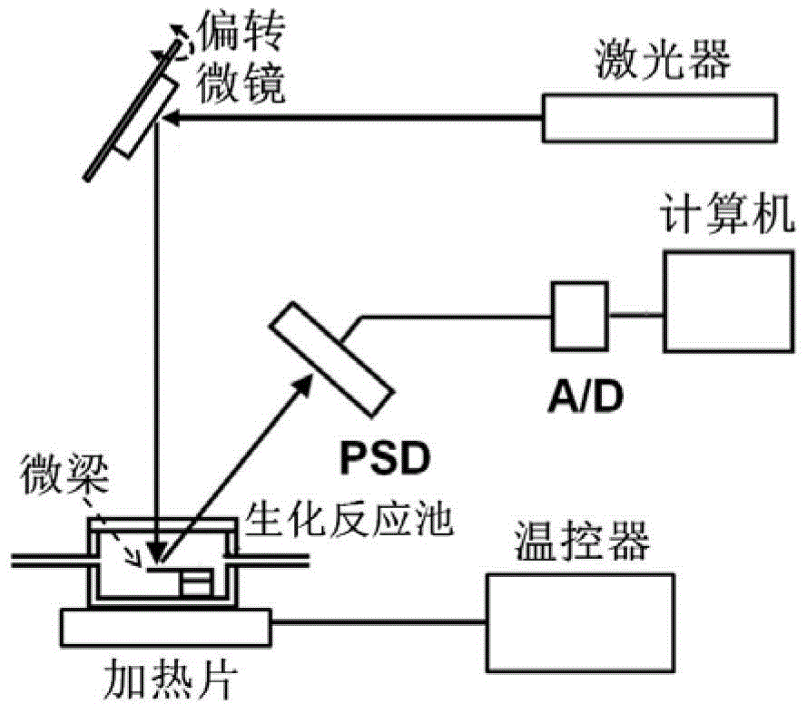
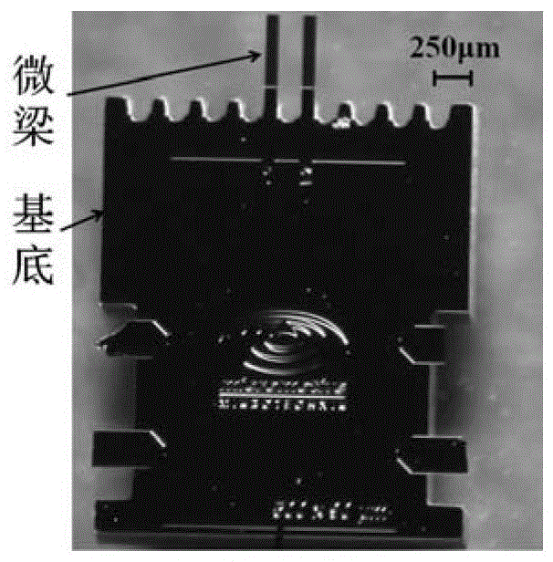
[0086] 1. A commercial microbeam array (German micromotive company, such as image 3 As shown, the microbeams are 500 μm long, 90 μm wide, and 1 μm thick, and the surface is coated with a 0.02 μm thick gold layer, and the center-to-center distance between two microbeams is 250 μm) fixed to the system (including lasers, deflection micromirrors, biochemical reaction pools) , thermostat, PSD, A / D converter, computer, such as figure 1 Shown) in the biochemical reaction pool.

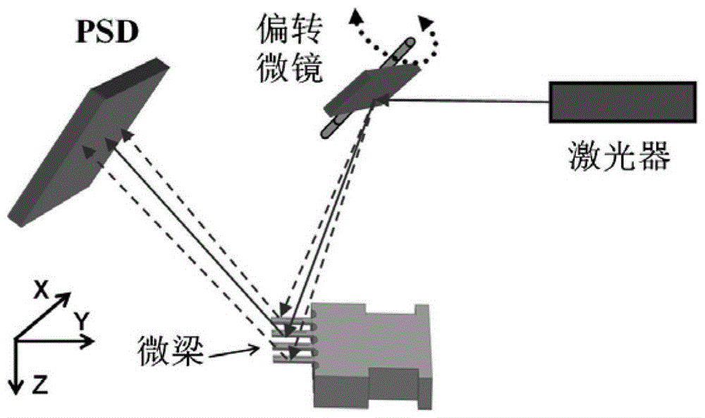
[0087] 2. The converging laser beam emitted by the semiconductor laser is deflected by the micromirror and then periodically scans two fixed points with a distance of 250 μm on the substrate of the microbeam array for 9 hours. The scanning displacement curve is as follows Figure 4 As shown: In the X direction and Y direction, the two scanning positions are kept parallel and consistent...

Embodiment 2

[0089] Example 2. Detection of Clenbuterol by Microbeam Array Biochemical Sensing Method Based on Microscope Scanning

[0090] 1. Experimental Setup and Reagents

[0091] The specific structure of the detection system is as follows: figure 1 As shown in , it mainly includes laser (parameters: diameter 8mm, length 20mm, wavelength of laser emission is 650nm, laser focus spot diameter is 200μm), deflection micromirror (parameters: driving voltage 40V~50V, driving frequency 3KHz, scanning angle range 10°), biochemical reaction pool (volume 0.5mL, fully sealed, composed of a 1mm inner diameter sample inlet, an inner diameter 1mm sample outlet, a glass sheet, and a microbeam fixing table, Figure 9 ), temperature controller (temperature control accuracy 0.01℃, temperature control range 0℃~100℃), PSD (displacement resolution 1μm, target surface size 12mm×12mm), A / D converter (12 bits), computer.

[0092] Clenbuterol antibody, clenbuterol standard sample CLEN, chloramphenicol stand...


PUM


Abstract

The invention relates to a micro cantilever beam array biochemical sensing device which comprises a reaction cell, a micro cantilever beam array, a semiconductor laser, a deflection micro-mirror, a signal generator, a photoelectric position sensitive detector (PSD) and a data processing device. The device utilizes deflection micro-mirror driving, achieves scanning detection of the micro cantilever beam array by a single focused laser beam, can achieve high-sensitivity, rapid and parallel detection of biochemical reaction information on the micro cantilever beam array, and can be applied in monitoring and detection of food safety, environmental pollution, biomedical sciences, scientific researches, production and manufacture and other fields. The invention also discloses a biochemical detection method utilizing the micro cantilever beam array biochemical sensing device.

Description

technical field [0001] The invention belongs to the technical field of biochemical sensing, and in particular relates to a microcantilever beam array biochemical sensing device and method, which can be applied to food safety, environmental pollution, biomedicine, scientific research, manufacturing and other fields. Monitoring and detection. Background technique [0002] The microcantilever (hereinafter referred to as microbeam) biochemical sensing technology based on surface stress detection is a new sensing technology that has emerged in recent years. Its principle is to immobilize the probe (antigen or antibody) molecule directly or indirectly. (Modification) on the gold-plated layer on one side of the microbeam, when the target molecules in the sample liquid to be detected react specifically with the probe molecules on the gold surface of the microbeam, the surface stress of the microbeam will change, resulting in microbeam Bending deformation, the process of detecting t...

Claims


Application Information

Patent Timeline
Patent Type & Authority Patents(China)
IPC IPC(8): G01N21/47G01N33/53G01B11/16
Inventor 张青川邬林程腾
Owner UNIV OF SCI & TECH OF CHINA
Why Eureka
Try Eureka