Bone scaffold forming system

A bone scaffold and model technology, applied in the field of biomedical tissue engineering, can solve the problem of lack of individual matching

Inactive Publication Date: 2014-06-25
SHENZHEN INST OF ADVANCED TECH
View PDF3 Cites 13 Cited by
  • Summary
  • Abstract
  • Description
  • Claims
  • Application Information

AI Technical Summary

Problems solved by technology

However, in the traditional preparation methods and technologies of porous scaffolds for tissue engineering, more attention is paid to the selection of pore-forming methods and the change of porosity, while relatively little attention is paid to the formation technology of scaffold shapes, which lacks individual matching.

Method used


Image

  • Bone scaffold forming system
  • Bone scaffold forming system

Examples


Embodiment 1

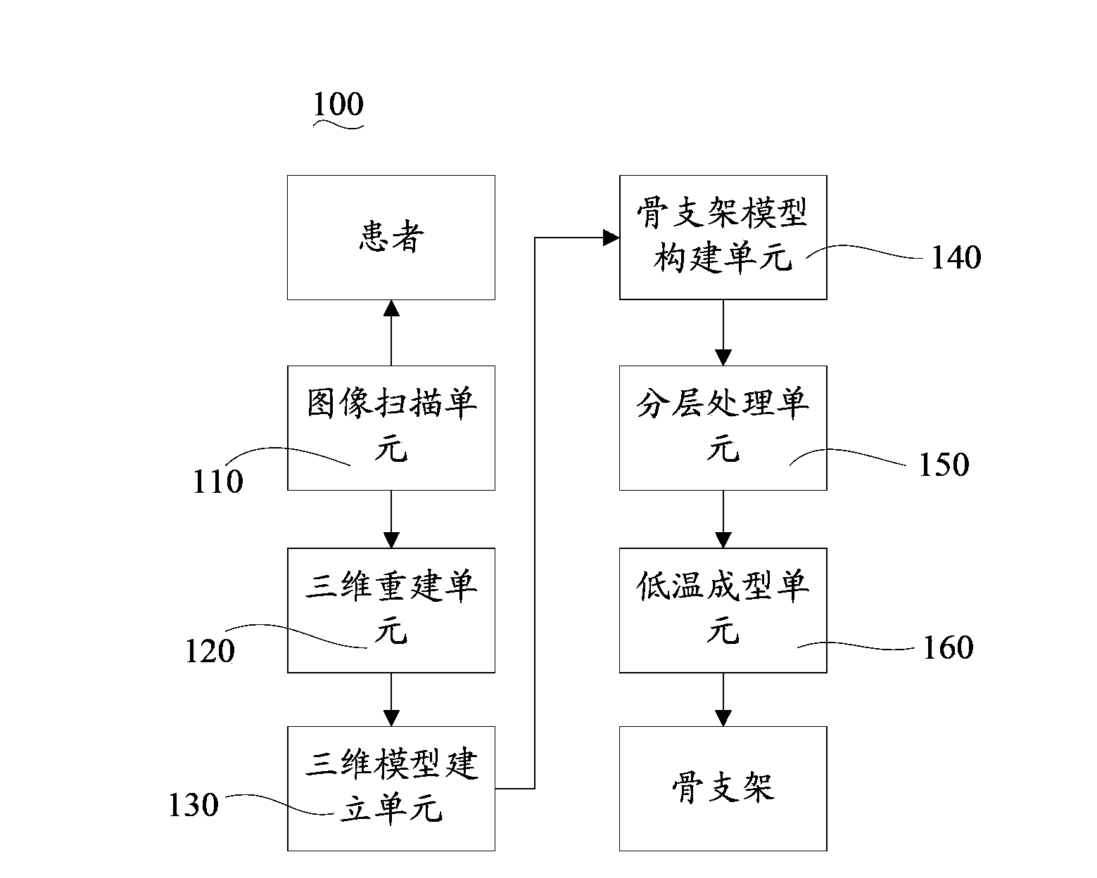
[0037] 1. Through CT scanning of the necrotic part of the femoral head of the patient, the scanning interval is 0.70mm, and the two-dimensional CT image data is obtained, which is stored in the U disk in dicom format; the data is read, segmented and three-dimensionally reconstructed with Mimics software; extracted The grayscale threshold range for the distal femur was 769-1023. After the three-dimensional defect part model is established, the software mirror function and transparency function are used to cut and separate along the overlapped edge contour line, extract the three-dimensional restoration model, and generate an STL format file.

[0038] 2. Read the above files with Solidworks software, optimize the macrostructure of the prosthetic model and perform hierarchical processing, and output the files in CLI format.

[0039] 3. Prepare material solution: weigh 20g of polyglycolic acid-lactic acid copolymer, 5g of finely ground hydroxyapatite, and 5g of icariin according to...

Embodiment 2

[0044] 1. Through CT scanning of the patient's bone defect, the scanning interval is 0.75mm, and the two-dimensional CT image data is obtained, which is stored in the U disk in dicom format; the data is read, segmented and three-dimensionally reconstructed with Mimics software; the proximal tibial bone is extracted The grayscale threshold range at the end is 567-2014. After the three-dimensional defect part model is established, the software mirror function and transparency function are used to cut and separate along the overlapped edge contour line, extract the three-dimensional restoration model, and generate an STL format file.

[0045] 2. Read the above files with Solidworks software, optimize the macrostructure of the prosthetic model and perform hierarchical processing, and output the files in CLI format.

[0046] 3. Preparation of material solution: Weigh 20g of polylactic acid, 10g of finely ground calcium sulfate, and 5g of icariin according to mass percentage, put t...

Embodiment 3

[0051] 1. Through CT scanning of the patient's bone defect, the scanning interval is 0.65mm, and the two-dimensional CT image data is obtained, which is stored in the U disk in dicom format; the data is read, segmented and three-dimensionally reconstructed with Mimics software; the proximal tibial bone is extracted The grayscale threshold range at the end is 567-2014. After the three-dimensional defect model is established, use the software mirror function and transparency function to cut and separate along the overlapped edge contour line, extract the restoration model, and generate an STL format file.

[0052] 2. Read the above files with Solidworks software, optimize the macrostructure of the prosthetic model and perform hierarchical processing, and output the files in CLI format.

[0053] 3. Prepare the material solution: weigh 20g of polyglycolic acid, 1 part of finely ground tricalcium phosphate powder, 5g of icariin according to the mass percentage, put the above mixtu...


PUM

PropertyMeasurementUnit
particle size (mesh)aaaaaaaaaa
pore sizeaaaaaaaaaa

Abstract

The invention relates to a bone scaffold forming system comprising an image scanning unit, a three-dimensional reconstruction unit, a three-dimensional model building unit, a bone scaffold model building unit, a hierarchical processing unit and a low-temperature forming unit. By the aid of the bone scaffold forming system, scanning imaging is performed on the bone injury part of a patient before bone scaffold forming by means of medical imaging technology so as to obtain image data of the bone injury part, then the acquired image data are subjected to modular processing to obtain hierarchical data of a to-be-repaired bone scaffold model, bone formation materials are utilized to prepare a bone scaffold exactly matched with the bone defect part of the patient in size and shape by the low-temperature forming unit through the hierarchical data, and accordingly the bone scaffold matched with the implanting part is prepared for the patient in vitro before surgery implementation to the benefit of shortening implementing time, further implant materials are enabled to be closely bonded with the defect part to promote bone formation.

Description

technical field [0001] The invention relates to the field of biomedical tissue engineering, in particular to a bone scaffold forming system. Background technique [0002] With the increase of bone defect cases caused by physical trauma, tumor diseases, etc., porous bone scaffolds formed by metal implants (such as pure titanium or titanium alloys) with good biocompatibility and stability are widely used in clinical practice. . However, in the traditional preparation methods and technologies of porous scaffolds for tissue engineering, more attention is paid to the selection of pore-forming methods and the change of porosity, while relatively little attention is paid to the formation technology of scaffold shapes, which lacks individual matching. Contents of the invention [0003] Based on this, a bone scaffold molding system with high individual matching is necessary. [0004] A bone scaffold forming system comprising: [0005] An image scanning unit is used to scan and i...

Claims


Application Information

Patent Timeline
Patent Type & Authority Applications(China)
IPC IPC(8): A61F2/28A61L27/18A61L27/12A61L27/54
CPCA61F2/28A61F2002/30001
Inventor 张明赖毓霄秦岭陈淑奎张鹏陈诗慧
Owner SHENZHEN INST OF ADVANCED TECH
Why Eureka
Try Eureka