Spraying, grinding and throwing abrasive belt flap wheel in gas phase and solid phase

The technology of sheet wheel and abrasive belt is applied in the design and manufacture of abrasive belt sheet wheel for high-speed grinding and polishing of difficult-to-machine materials, which can solve the problems of poor surface roughness, difficulty in meeting design requirements for surface integrity indexes, and high grinding and polishing temperature.

Inactive Publication Date: 2014-07-02
TIANJIN UNIV OF TECH & EDUCATION TEACHER DEV CENT OF CHINA VOCATIONAL TRAINING & GUIDANCE
View PDF0 Cites 4 Cited by
  • Summary
  • Abstract
  • Description
  • Claims
  • Application Information

AI Technical Summary

Problems solved by technology

However, when ordinary grinding wheels and abrasive belt wheels are used for dry grinding and polishing of high-strength, high-toughness and difficult-to-machine materials, the processed surface roughness is poor, and scratches are prone to occur, and the grinding wheel or abrasive belt wheels passivate quickly, resulting in large losses and large margins. It is difficult to remove, and at the same time, the grinding wheel or the abrasive belt wheel adheres, resulting in high grinding and polishing temperature, and the ti

Method used


Image

  • Spraying, grinding and throwing abrasive belt flap wheel in gas phase and solid phase

Examples


specific Embodiment approach

[0030] Below in conjunction with accompanying drawing, introduce the content of the present invention in detail.

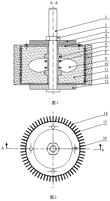
[0031] Figure 1 and figure 2 As shown, the gas-solid two-phase internal abrasive blasting belt wheel is mainly composed of the abrasive belt plate 14, the abrasive belt wheel mandrel 1 and the internal spray lubrication cavity structure, the internal spray lubrication cavity is mainly the differential fan 9, the lubrication The medium 11, the lubricating channel 12, the cover plate 4 and the base 12 are composed. The outer edge of the base 12 is evenly processed with lubricating channels 10 , and within the interval of the lubricating channels 12 , the abrasive belt sheets 14 are evenly bonded to the outer edge surface of the base 12 .

[0032] During installation, first the lower supporting plate 13 is installed on the leaf wheel mounting handle 1, then the base 12 bonded with the abrasive belt sheet 14 is installed on the lower supporting plate 13, and then the...


PUM


Abstract

The invention relates to a spraying abrasive belt flap wheel in gas phase and solid phase for drying type polishing and throwing, wherein the spraying abrasive belt flap wheel is mainly oriented to machining of high-strength and high-tenacity materials difficult to machine. Fan blades and an inner cavity structure for differential rotation of a chassis of the abrasive belt flap wheel are introduced into manufacturing of the abrasive belt flap wheel. The abrasive belt flap wheel is mainly composed of an abrasive belt flap wheel mounting handle, the chassis, a cover disk, the differential fan blades, abrasive belt blades and other parts. In the grinding and throwing process, a main shaft of a machine tool drives the abrasive belt flap wheel mounting handle, a base, a cover plate and the like to rotate together at high speed, the differential blades of the inner cavity of the base are connected with a fan blade mounting sleeve, the rotating speed of the differential blades of the inner cavity of the base is not consistent with that of the abrasive belt flap wheel mounting handle so that driving force can be exerted on lubricating mediums filled in the inner cavity of the base, and the lubricating mediums are precipitated to the surface of the abrasive belt blades continuously and quantitatively under the joint action of the driving force and eccentric force. The abrasive belt flap wheel is simple in structure and easy to popularize, the lubricating mediums in the abrasive belt flap wheel can be reliably conveyed to the grinding and throwing arc area with low cost through the structure, and therefore the drying type polishing and throwing of the high-strength and high-tenacity materials difficult to machine can be achieved.

Description

technical field [0001] The invention relates to a gas-solid two-phase internal spray grinding and polishing belt wheel for grinding and polishing of high-strength, high-toughness and difficult-to-process materials. The driving force generated by the differential rotation of the inner cavity fan drives the solid lubricant in the inner cavity of the base of the abrasive belt wheel directly to the surface of the abrasive belt sheet to lubricate grinding and polishing and inhibit the adhesion of chips. It is especially suitable for the design and manufacture of abrasive belt wheels for high-speed grinding and polishing of difficult-to-machine materials. Background technique [0002] High-strength and high-toughness difficult-to-machine materials mainly include ultra-high-strength steel, titanium alloys, superalloys, etc., and their characteristics mainly include: high plasticity, good toughness, high strength, high strengthening coefficient, and low thermal conductivity. In the...

Claims


Application Information

Patent Timeline
IPC IPC(8): B24D13/04B24D13/06
Inventor 霍文国邵娟张翔宇蔡兰蓉董庆运
Owner TIANJIN UNIV OF TECH & EDUCATION TEACHER DEV CENT OF CHINA VOCATIONAL TRAINING & GUIDANCE
Why Eureka
Try Eureka