Heat energy power machine and working method thereof

A power machine and thermal energy technology, applied in the field of thermal power machines, can solve the problems of high cost and high manufacturing cost, and achieve the effects of low noise, simple machine structure and high economic benefits

Active Publication Date: 2014-07-09
郭远军
View PDF7 Cites 4 Cited by
  • Summary
  • Abstract
  • Description
  • Claims
  • Application Information

AI Technical Summary

Problems solved by technology

[0012] The invention overcomes the high cost of the expansion chamber, compression chamber, heater, cooling chamber, regenerator, etc. in the Stirling engine, and the heat loss is 2-3 times that of the internal combustion engine; it overcomes the need for an organic Rankine cycle system. Expander or steam turbine, a technical problem with high manufacturing costs

Method used


Image

  • Heat energy power machine and working method thereof
  • Heat energy power machine and working method thereof
  • Heat energy power machine and working method thereof

Examples


Embodiment approach

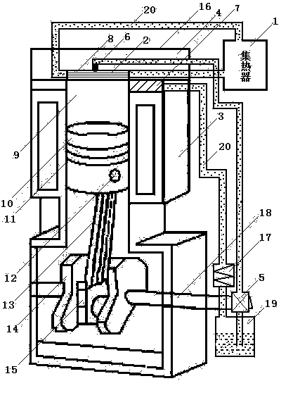
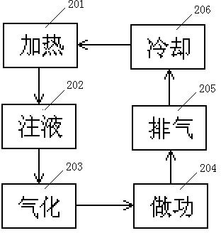
[0037] Refer to attached Figure 1-3 , the embodiment of the present invention is:

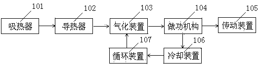
[0038]A thermal power machine, which consists of a heat absorber 1, a gasification heat conducting sheet 2, an insulation layer 3, a cylinder head 4, a pressure pump 5, an atomizer 6, an exhaust valve 7, a gasification reactor 8, a cylinder 9, and a piston 10. Piston ring 11, connecting pin 12, connecting rod 13, crankshaft 14, bearing 15, casing 16, cooler 17, transmission shaft 18, liquid storage tank 19 and pipeline 20, and cylinder 9 is provided with piston 10, The piston 10 is provided with a piston ring 11, the piston 10 is connected to the connecting rod 13 through the connecting pin 12, the connecting rod 13 is connected to the crankshaft 14, the crankshaft 14 is provided with a bearing 15, the bearing 15 is fixed on the transmission shaft 18, and the transmission shaft 18 is fixed on the machine through the bearing. On the shell 16, one end of the transmission shaft 18 is provided wi...


PUM


Abstract

The invention relates to a heat energy power machine and a working method thereof. The heat energy power machine comprises a heat absorber, a heat conducting device, a gasification device, a working mechanism, a cooling device, a transmission device and a circulating device. The heat energy power machine is characterized in that the heat absorber is connected with the heat conducting device through a pipeline, the heat conducting device is arranged on the gasification device connected with the working mechanism, the working mechanism is connected with the cooling device and the transmission device, the cooling device is connected with the circulating device connected with the gasification device, the transmission device is related to the circulating device, and the circulating device is turned on and off by one time every time circulation is completed. The heat energy power machine and the working method thereof have the advantages that working media are used circularly, and no pollution is caused; heat energy conversion efficiency ranges from 65% to 98%; output power can be adjusted; the machine is used for conducting gasification working on the working media, and detonation is not produced in the whole process; the machine is simple in structure, conventional energy consumption can be replaced, economic benefits are high, energy conservation and environmental protection are achieved, and noise is low.

Description

technical field [0001] The invention belongs to the field of thermal power machines, in particular to power machines that use solar energy, geothermal heat, high-temperature gas generated by combustible combustion, internal combustion engine heat or tail gas, and high-temperature gas discharged from factories to convert thermal energy into kinetic energy. Background technique [0002] Traditional power machines include steam engines, internal combustion engines, and external combustion engines. [0003] Steam engine: Inseparable from the boiler, the whole device is bulky and bulky; the pressure and temperature of the fresh steam cannot be too high, the exhaust pressure cannot be too low, and the thermal efficiency is difficult to improve; it is a reciprocating machine, and the inertia limits the increase of the speed; The working process is discontinuous, and the flow of steam is limited, which limits the improvement of power. [0004] Internal combustion engine: complex st...

Claims


Application Information

Patent Timeline
Patent Type & Authority Applications(China)
IPC IPC(8): F02G1/044
Inventor 郭远军
Owner 郭远军
Why Eureka
Try Eureka