Pack to Cell equalization circuit based on LC resonant converter and implementation method thereof

A technology of resonant transformation and equalization circuit, applied in circuit devices, battery circuit devices, current collectors, etc., can solve the problems of limited equalization current, energy waste, small equalization current, etc., to reduce circuit volume and cost, improve inconsistency, Overcome the effect of zero voltage difference

Active Publication Date: 2014-07-30
SHANDONG UNIV
View PDF6 Cites 18 Cited by
  • Summary
  • Abstract
  • Description
  • Claims
  • Application Information

AI Technical Summary

Problems solved by technology

[0008] 1) The open circuit voltage of lithium-ion batteries is relatively flat when the SOC is between 30% and 70%. Even if the SOC differs greatly, the corresponding voltage difference is very small. The current is very small, which may even cause the power electronic devices to fail to conduct normally;
[0009] 2) Due to the conduction voltage drop of power electronic devices, it is difficult to achieve zero voltage difference balance between battery cells
However, the main problem of this invention is: because it belongs to the Cell to Cell type equalization circuit, even if the Boost boost conversion is used, the improved equalization current is limited, which is far from being able to meet the equalization requirements of the large-capacity power battery of the electric vehicle, and the Boost Boost conversion itself also has energy waste

Method used


Image

  • Pack to Cell equalization circuit based on LC resonant converter and implementation method thereof
  • Pack to Cell equalization circuit based on LC resonant converter and implementation method thereof
  • Pack to Cell equalization circuit based on LC resonant converter and implementation method thereof

Examples


Embodiment 1

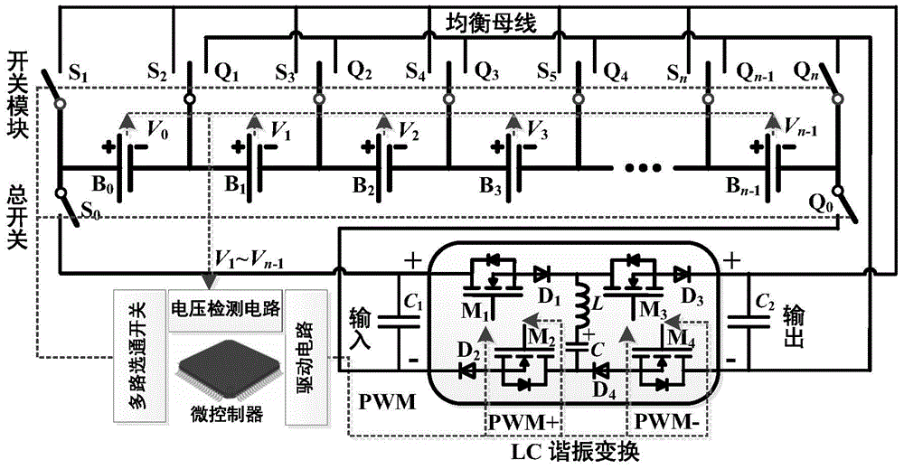
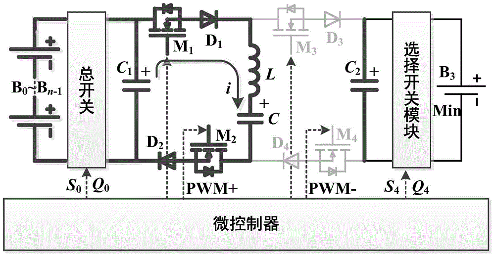
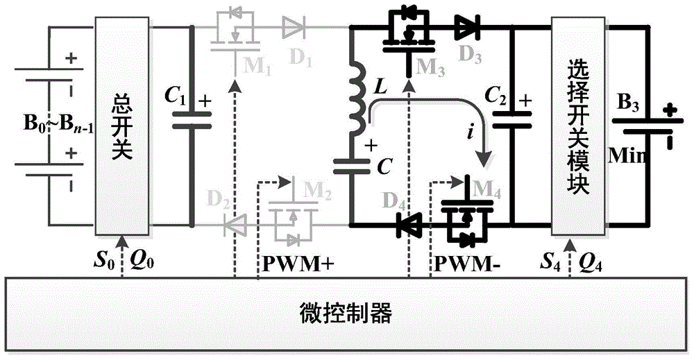
[0068] Take 8 cells as an example, and assume B 3 It is the battery cell with the lowest voltage.

[0069] The microcontroller of the equalization circuit adopts digital signal processing DSP (TMS320F28335), which has high-precision AD sampling and PWM output; the multi-channel strobe switch adopts CD4051, which is a single 8-channel digital control analog electronic switch, with A, B and C three The binary control input terminal and EN have a total of 4 inputs, with low on-resistance and very low cut-off leakage current; the voltage detection circuit uses Linear Technology's LTC6802 dedicated voltage measurement chip to measure the voltage of each battery in the battery pack in real time.

[0070] The selector switch module uses a relay with a pair of normally open contacts, its model is HJR1-2C L-05V, figure 1 Medium (S i , Q i )(i=1,2,3...,n) are a pair of normally open switches. The microcontroller controls its conduction or closure through a multi-channel strobe switc...


PUM


Abstract

The invention discloses a Pack to Cell equalization circuit based on an LC resonant converter and an implementation method of the Pack to Cell equalization circuit based on the LC resonant converter. The equalization circuit mainly comprises a microcontroller, a selective switch module, a master switch, an equalization bus-bar, the LC resonant converter and filter capacitors. A battery single body with the lowest voltage is strobed into the equalization bus-bar by the microcontroller and is connected with the output of the LC resonant converter, and the positive electrode and the negative electrode of a battery set is connected with the input of the LC resonant converter by controlling opening and closing of the master switch. Meanwhile, the microcontroller sends a pair of PWM signals which are complementary in state to control the LC resonant converter to alternately work in a charging state or in a discharging state so as to achieve equalization of zero current switching. The Pack to Cell equalization circuit based on the LC resonant converter and the implementation method of the Pack to Cell equalization circuit based on the LC resonant converter effectively improve inconsistency among the battery signal bodies, enhance equalization efficiency, increase equalization currents, shorten equalization time, achieve equalization of zero current switching, reduce energy dissipation, reduce the number of switches and reduce the circuit size and cost.

Description

technical field [0001] The invention relates to a Pack to Cell equalization circuit based on LC resonance conversion and a realization method. Background technique [0002] Energy crisis and environmental pollution are two major problems facing the world today. Electric vehicles are widely welcomed by people for their energy saving and environmental protection, and have become the inevitable trend of future automobile development. Lithium-ion batteries are widely used as power sources in electric vehicles and hybrid electric vehicles because of their high energy density, low discharge rate and no memory effect. However, due to the technical constraints of battery manufacturing technology and power management system, a large number of monomers and multi-stage series-parallel connections are required to provide sufficient supply voltage and driving power during the use of power batteries. However, when this type of battery is used in series, it is easy to cause overcharge an...

Claims


Application Information

Patent Timeline
Patent Type & Authority Applications(China)
IPC IPC(8): H02J7/00
Inventor 张承慧商云龙崔纳新纪祥
Owner SHANDONG UNIV
Why Eureka
Try Eureka