
Stray light removing hard tube endoscope optical system

A technology of optical system and endoscope, which is applied in the field of optical system, can solve serious and stray light problems, achieve good image quality, uniform brightness, and eliminate the interference of stray light

Inactive Publication Date: 2014-08-06
BEIJING WEISIDUN ASIA PACIFIC OPTO ELECTRIC INSTR CO LTD
View PDF5 Cites 7 Cited by
  • Summary
  • Abstract
  • Description
  • Claims
  • Application Information

AI Technical Summary

Problems solved by technology

[0003] Although the manufacturing and processing technology of medical endoscopes is quite mature, some existing endoscope products have serious stray light problems.

Method used


Image

  • Stray light removing hard tube endoscope optical system
  • Stray light removing hard tube endoscope optical system
  • Stray light removing hard tube endoscope optical system

Examples


Embodiment 1

[0035] Such as figure 2 As shown, in this embodiment, see Table 1 for the structural parameters of the endoscope.

[0036] Table 1

[0037]

[0038] In the above table 1, r represents the radius of curvature of each surface of the lens group, in mm; d represents the surface spacing of each lens surface of the lens group on the optical axis, in mm; nd represents the relative d light of the lens material (wavelength is 587.6 nm) Refractive index; vd represents the Abbe number of the lens material relative to d light.

[0039] Such as Figure 5 as shown, Figure 5 It is an aberration diagram of an embodiment of the present invention, wherein (A) is spherical aberration, (B) is astigmatism, and (C) is distortion; the aberration in each aberration diagram takes d light as a reference wavelength, and spherical aberration represents The aberration of C light and F light is shown, D represents the diameter of the entrance pupil, and 2ω represents the full field of view.

[00...

Embodiment 2

[0042] Such as Figure 8 As shown, in this embodiment, see Table 2 for the structural parameters of the endoscope.

[0043] Table 2

[0044]

[0045]

[0046] In the above Table 2, r represents the radius of curvature of each surface of the lens group, and the unit is mm; d represents the surface spacing of each lens surface of the lens group on the optical axis, and the unit is mm; nm) Refractive index; vd represents the Abbe number of the lens material relative to d light.

[0047] Such as Figure 11 as shown, Figure 11 It is an aberration diagram of an embodiment of the present invention, wherein (A) is spherical aberration, (B) is astigmatism, and (C) is distortion; the aberration in each aberration diagram takes d light as a reference wavelength, and spherical aberration represents The aberration of C light and F light is shown, D represents the diameter of the entrance pupil, and 2ω represents the full field of view.

[0048] Such as Figure 12 as shown, Fig...


PUM


Abstract

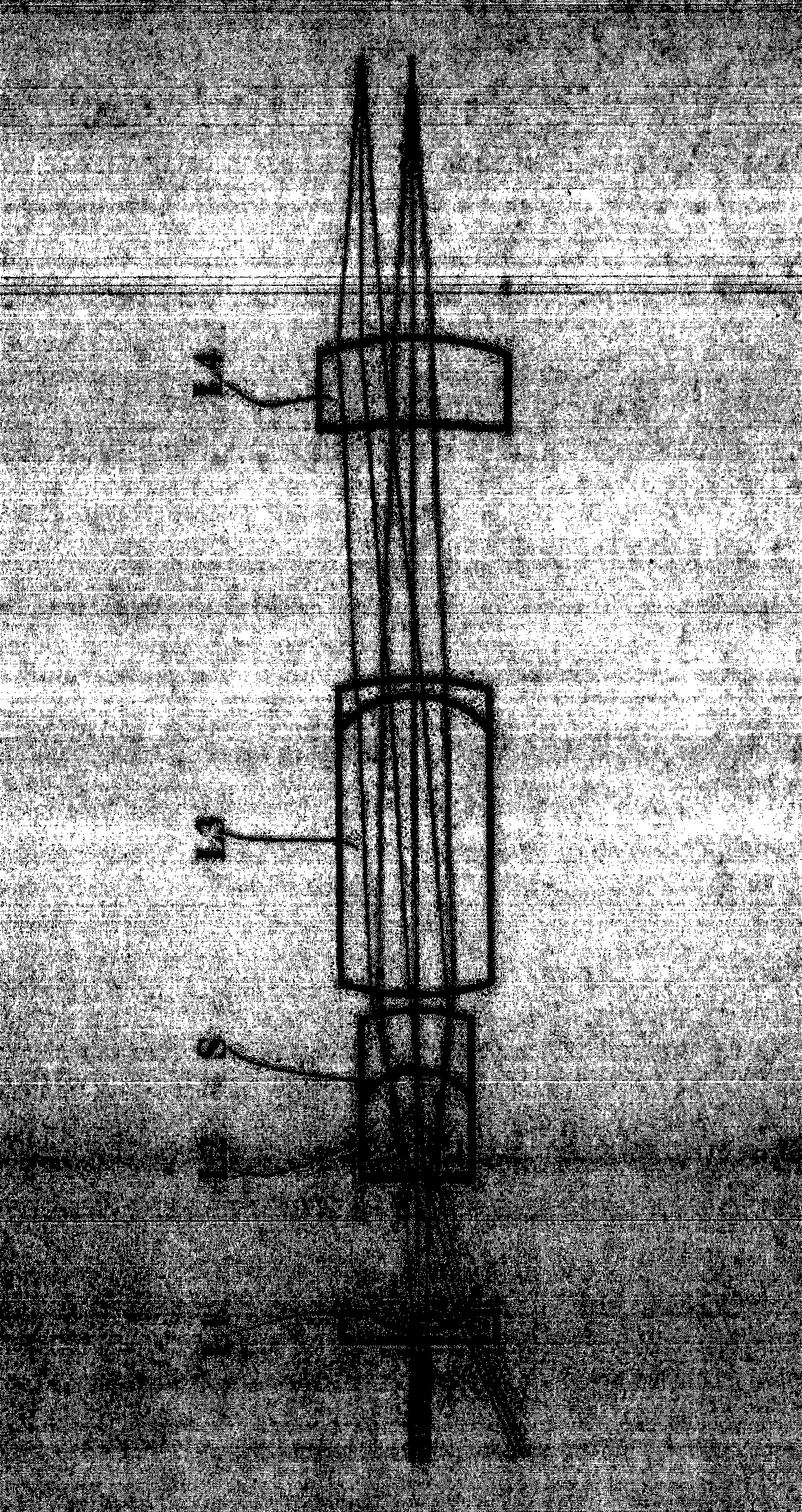
The invention provides an optical system of a hard tube endoscope. The optical system comprises an objective lens set and a relay system. The objective lens set comprises a first lens set, a second lens set, a third lens set and a fourth lens set. An aperture diaphragm is located in the second lens set. The relay system is composed of odd number pairs of transferring lens with the magnifying power being 1:1, the relay system comprises two completely same tri-agglutination bar lenses, the distances between every two adjacent bar lenses are equal, and images formed by objective lenses are transferred in a working telescope many times. A final image is received through the ocular lens human eye or a CCD detector. The full field angle of the system is within 70 degrees, stray light does not exist in an image plane when the system aligns with a light source, the interference on imaging from the stray light entering a lens cone is completely removed, the MTF value is larger than 0.3 at the 1,201p / mm position, and the optical system has the advantages of being large in visual field and field depth, small in field curvature, capable of removing distortion, even in brightness, simple in structure, low in cost and the like. The picture 1 is the structural representation of the optical system of the non-stray-light hard tube endoscope, and the number 1 is the objective lens set.

Description

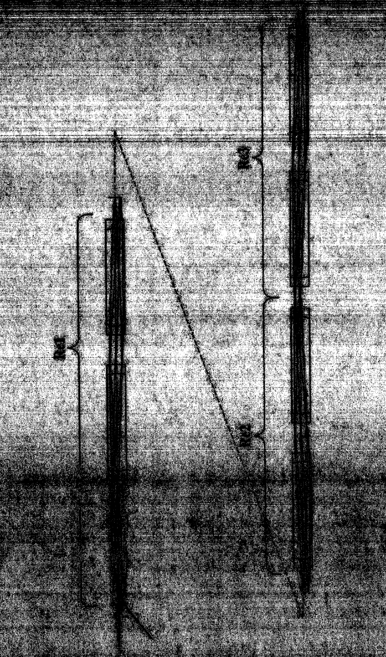
technical field [0001] The invention relates to an optical system of a rigid tube endoscope, in particular to an endoscope optical system capable of eliminating stray light, large field of view, large depth of field, small field curvature, distortion elimination, uniform brightness, simple structure and low cost. system. Background technique [0002] Medical endoscope is a device that enters the human body through natural channels or minimally invasive incisions for observation and treatment. It uses multiple sets of relay lens groups to transmit the image formed by the objective lens multiple times in the slender lens barrel, and finally reaches the human eye through the eyepiece or is received by the CCD detector. [0003] Although the manufacturing and processing technology of medical endoscopes is quite mature, some existing endoscope products have serious stray light problems. Such as figure 1 As shown in the figure, when an endoscope product is aimed at a distant li...

Claims


Application Information

Patent Timeline
Patent Type & Authority Applications(China)
IPC IPC(8): G02B23/24G02B13/06G02B27/00
Inventor 王涌天禹璐程德文刘小华
Owner BEIJING WEISIDUN ASIA PACIFIC OPTO ELECTRIC INSTR CO LTD
Learn More