Sludge multi-effect drying incineration treatment system and application method thereof

A treatment system and sludge technology, applied in combustion methods, dewatering/drying/concentrating sludge treatment, incinerators, etc., can solve the problems of difficult treatment cost of odorous flue gas, low production capacity, difficulty in large-scale, etc. The effect of drying energy saving, high drying efficiency and large production capacity

Inactive Publication Date: 2014-09-03
王子国
View PDF6 Cites 35 Cited by
  • Summary
  • Abstract
  • Description
  • Claims
  • Application Information

AI Technical Summary

Problems solved by technology

It can be seen that because the invention uses flue gas as the carrier gas to directly supply heat and enter the dryer for drying, it has the advantages and disadvantages of using flue gas as the heat medium to directly contact the convection heat drying technology, that is, the drying efficiency is high, but most of them contain stinky smoke It is difficult or costly to treat the gas thoroughly, the wet steam in the dry gas has a low dew point and it is difficult to condense cascade utilization, the

Method used


Image

  • Sludge multi-effect drying incineration treatment system and application method thereof
  • Sludge multi-effect drying incineration treatment system and application method thereof
  • Sludge multi-effect drying incineration treatment system and application method thereof

Examples


Embodiment 1

[0092] In this embodiment, the combined drying system adopts a 2-stage air-flow bed drying subsystem to dry the sludge and then incinerate it.

[0093] The process flow is connected as follows:

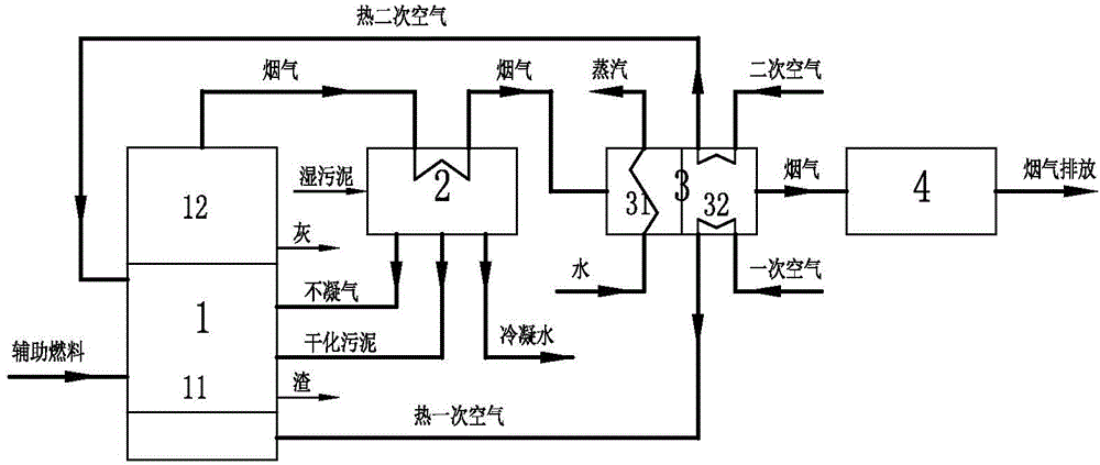
[0094] See figure 1 , figure 2 : Including an incineration system 1, a combined drying system 2, a flue gas waste heat recovery system 3, and a flue gas treatment and discharge system 4. The incineration system 1 includes a fluidized bed incinerator 11 and a high-temperature dust collector 12; the flue gas waste heat recovery system 3 includes a steam boiler 31 and an air preheater 32;

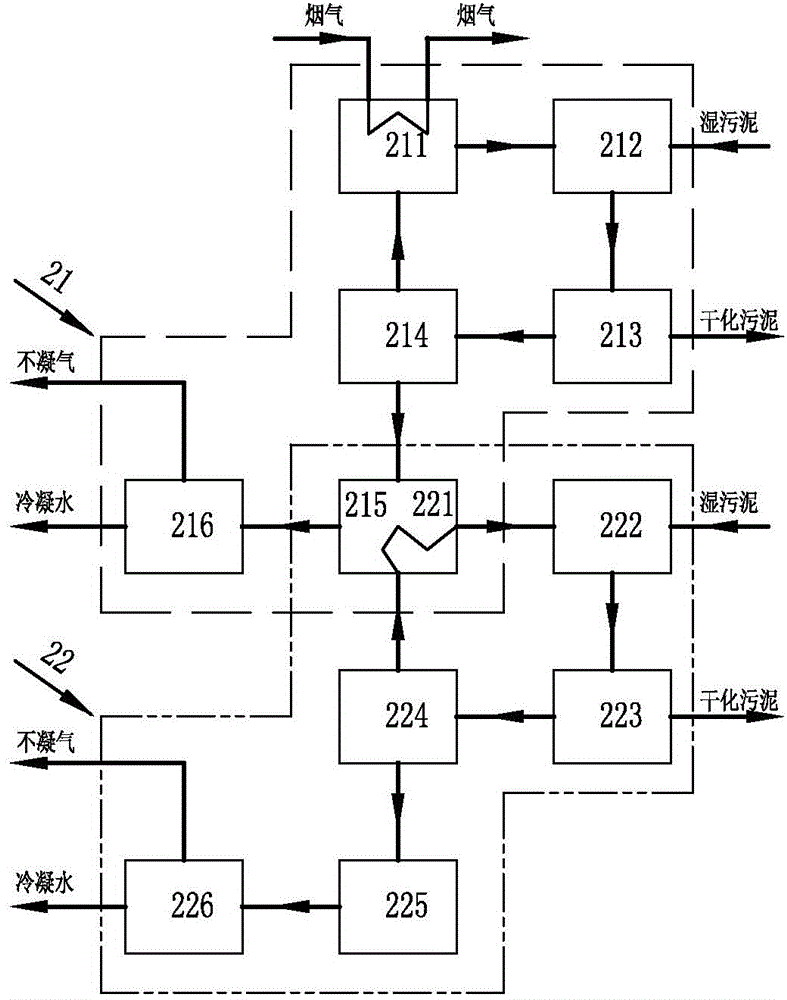
[0095] In this embodiment, the combined drying system 2 is composed of two-stage air-flow bed drying subsystems, the first-stage air-flow bed drying subsystem 21 and the second-stage air-flow bed drying subsystem 22 . The first-stage air-flow bed drying subsystem 21 is composed of a carrier gas heat exchanger 211, an air-flow bed dryer 212, a drying dust collector 213, a drying fan 214, a dry gas ...

Embodiment 2

[0112] The combined drying system of this embodiment uses a 3-stage air-flow bed drying subsystem to dry the sludge and then incinerate it.

[0113] The process flow is connected as follows:

[0114] See figure 1 , image 3 : Including an incineration system 1, a combined drying system 2, a flue gas waste heat recovery system 3, and a flue gas treatment and discharge system 4. The incineration system 1 includes a fluidized bed incinerator 11 and a high-temperature dust collector 12; the flue gas waste heat recovery system 3 includes a steam boiler 31 and an air preheater 32;

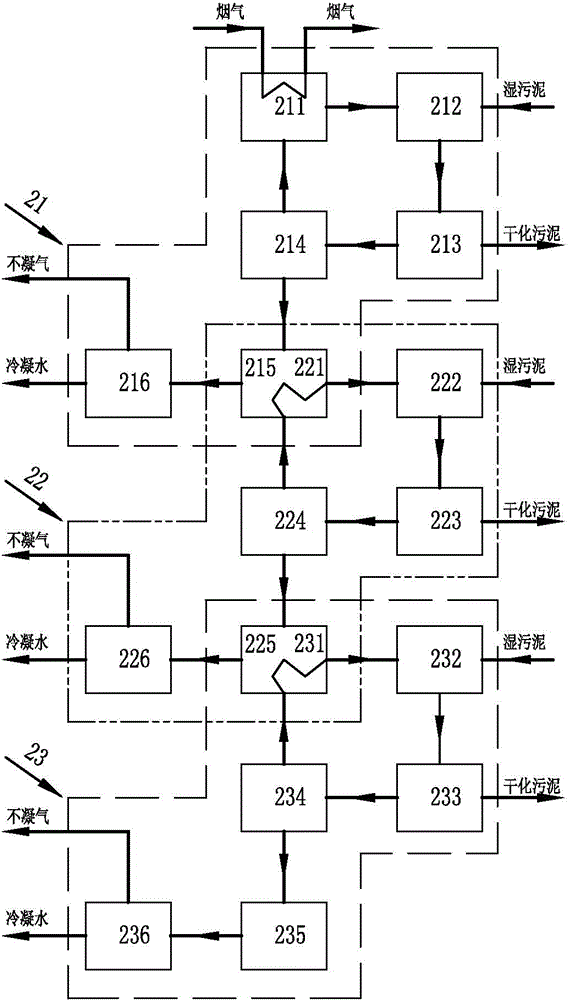
[0115] In this embodiment, the combined drying system 2 is composed of three-stage air-flow bed drying subsystems, the first-stage air-flow bed drying subsystem 21 , the second-stage air-flow bed drying subsystem 22 , and the third-stage air-flow bed drying subsystem 23 .

[0116] The first-stage air-flow bed drying subsystem 21 is composed of a carrier gas heat exchanger 211, an air-flow bed dryer 21...


PUM


Abstract

The invention discloses a sludge multi-effect drying incineration treatment system and an application method thereof. The system comprises an incineration system, a combined drying system, a flue gas waste heat recycling system and a flue gas treatment discharging system. According to the system, the heat is transferred into a combined gas bed drying process of a hot carried gas by one step through a dividing wall by virtue of high-temperature flue gas obtained via the incineration of the sludge. Thus, the system has the advantages of high heat-transfer drying efficiency, safety, explosion resistance, large production capacity, low large-scale investment of a sludge treatment device, gradient utilization of heat energy of dry waste steam and good energy conservation effect; a dry smelly non-condensable gas which is sent into a fluidized bed incinerator can be completely deodorized.

Description

technical field [0001] The invention belongs to the field of environmental protection, and in particular relates to a system and a use method for multi-effect drying and incineration treatment of sludge. Background technique [0002] In the fields of energy, chemical industry, textile printing and dyeing, papermaking, municipal administration, environmental protection and other fields, a large amount of sludge with high moisture content is usually produced. At present, the amount of sludge produced by municipal and industrial sewage treatment is the largest. With the acceleration of urbanization in my country and the continuous construction of sewage treatment plants, the amount of industrial and domestic sewage treatment in China is increasing rapidly, and more sludge will be generated. [0003] The composition of sludge is very complex. In addition to a large amount of water, it also contains a large amount of organic matter, refractory organic matter, various trace elemen...

Claims


Application Information

Patent Timeline
IPC IPC(8): C02F11/12F23G7/00
CPCY02E20/12Y02P20/10
Inventor 王子国艾伟
Owner 王子国
Why Eureka
Try Eureka