Multi-function heat-pump boiled water device

A water boiling device and multi-functional technology, applied in the field of energy-saving drinking water devices, can solve the problems of incomplete heat recovery, limited cooling range, unsatisfactory energy-saving effect, etc., and achieve the effect of waste heat recovery and utilization and power consumption reduction

Active Publication Date: 2014-09-03
江苏乐普四方科技有限公司
View PDF6 Cites 3 Cited by
  • Summary
  • Abstract
  • Description
  • Claims
  • Application Information

AI Technical Summary

Problems solved by technology

The Chinese patent with the application number 201210456909.9 only uses a heat pump to preheat the water, and the energy saving effect is not ideal; in addition, the treatment process of the warm boiled water relies on the heat exchange when the tap water flows, the cooling range is limited, and the heat recovery is not complete; In addition, the heat preservation of the boiling water tank is assisted by electric heating to increase the temperature. When the electric heating tube is working, the surface temperature exceeds 100°C. The water in contact with the surface is still boiling, and there are unhealthy factors such as thousands of boiling water.
The Chinese patent application number 201220232076.3 uses the principle of air source heat pump to directly boil water, but its core heat pump system is a set of cascade heat pump heating system. The system is too complicated and the production cost is too high for practical application. It is suitable for industrial mass production, and the energy saving effect is not ideal; at the same time, the patent has a single function, only has the function of boiling water, and cannot meet the diverse needs of different customers

Method used


Image

  • Multi-function heat-pump boiled water device

Examples


Embodiment Construction

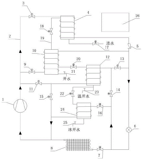
[0018] The present invention will be specifically introduced below in conjunction with the accompanying drawings and specific embodiments.

[0019] see figure 1 , The heat pump water boiling device of the present invention includes three parts: a heat pump system, a water system and a control system 26 . Wherein, the water system includes a water boiler 4, a high-temperature boiling water tank 10, a medium-temperature boiling water tank 12, and an ice boiling water tank 24 connected in series in sequence. The high-temperature and high-pressure refrigerant in the system performs heat exchange, and the tap water is heated to boiling water above 95°C; the boiling water enters the high-temperature boiling water tank 10 through the second waterway control valve 18, and part of the high-temperature boiling water is stored in the high-temperature boiling water tank 10, and some of the high-temperature boiling water is stored in the high-temperature boiling water tank 10. Boiled wate...


PUM


Abstract

The invention discloses a multi-function heat-pump boiled water device which comprises a control system, a heat pump system and a water system, wherein the water system comprises a water boiler, a high-temperature boiled water tank, a medium-temperature boiled water tank and an ice boiled water tank, which are sequentially connected in series through water system pipelines; the heat pump system comprises a compressor, a throttle mechanism and a hot source heat exchanger, which are connected through heat pump system pipelines. The multi-function heat-pump boiled water device has the benefits that the heat-pump boiled water device can simultaneously provide boiled water, warm water and ice water, is sanitary and healthy, meets diversified demands of different clients, and is particularly suitable for places such as markets, wine shops, drink shops, airports, stations, factories and enterprises needing abundant boiled water; water boiling, temperature rising and temperature lowering are completed through the same one set of heat pump system, and waste heat recovery is realized well; compared with the traditional electric heating water boiler, the power consumption can be reduced by about 70 percent, energy conservation and emission reduction are realized; the heat-pump boiled water device conforms to a new concept of national energy-conservation industrial policy and social energy conservation and environmental protection.

Description

technical field [0001] The invention relates to a water boiling device, in particular to a multifunctional energy-saving drinking water device. Background technique [0002] Most of the current water boiling devices are electric heating, and a few of them use direct fuel heating. Their common disadvantage is high energy consumption, and fuel heating water boilers will also cause environmental pollution, which does not meet the energy-saving and environmental protection requirements proposed by the state. [0003] According to people's living habits and health requirements, generally speaking, drinking water is mostly boiled water, but the water temperature immediately after boiling is as high as 90-95°C, which cannot be directly imported. Usually, the water temperature that people can directly drink It is about 60°C. Therefore, the entire physical process of drinking water is a process of heating up and then cooling down. The traditional heating method is used for heating u...

Claims


Application Information

Patent Timeline
IPC IPC(8): F24H4/04F25D31/00
CPCY02P80/10
Inventor 郭永孙海龙文立宁
Owner 江苏乐普四方科技有限公司
Why Eureka
Try Eureka