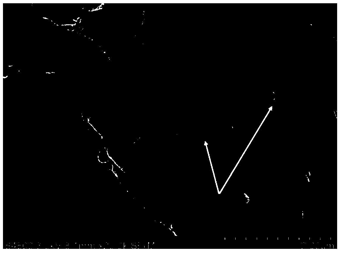
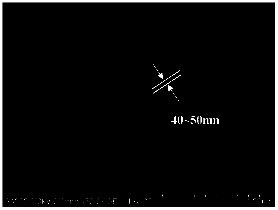
Silicon dioxide composite anode material for lithium ion battery, as well as preparation method and application of silicon dioxide composite anode material

A lithium-ion battery and silicon oxide technology, applied in battery electrodes, secondary batteries, electrochemical generators, etc., can solve the problems of materials without conductivity, improvement, and difficult control of grains, so as to improve electronic conductivity Effect

Active Publication Date: 2014-09-03
BTR NEW MATERIAL GRP CO LTD +1
View PDF13 Cites 63 Cited by
  • Summary
  • Abstract
  • Description
  • Claims
  • Application Information

AI Technical Summary

Problems solved by technology

[0011] As far as the SiO materials used in previous literature and patent reports are concerned, the capacity is generally less than 1500mAh/g, and the efficiency is lower than 75.0%. Compared with the theoretical value, there is still room for improvement; at the same time, related literature reports that the electrical conductivity of SiO materials is extremely poor. , the order of magnitude of conductivity is in the range of insulators (-12 S/cm)
[0012] CN103236517A discloses a silicon-based negative electrode material for a lithium-ion battery and a preparation method thereof. The silicon-based negative electrode material for a lithium-ion battery is made of silicon monoxide, the macroscopic particle size is 10-25 μm, and the microscopic structure is silicon dioxide-coated Covered with nano-silicon particles, the particle size of the inner silicon particles is 20-30nm; the negative electrode material has an initial discharge capacity of 2010-2640mAh/g at a rate of 0.1C, and 420-790mAh/g after 50 cycles; the SiO The reversible capacity of the material is less than 1500mAh/g, and the initial efficiency is obviously less th

Method used


Image

  • Silicon dioxide composite anode material for lithium ion battery, as well as preparation method and application of silicon dioxide composite anode material
  • Silicon dioxide composite anode material for lithium ion battery, as well as preparation method and application of silicon dioxide composite anode material
  • Silicon dioxide composite anode material for lithium ion battery, as well as preparation method and application of silicon dioxide composite anode material

Examples


Example Embodiment

[0096] Example 1

[0097] Mix silicon dioxide and metal silicon at a molar ratio of 1:1, and make them react at 1350°C under 100Pa to produce silicon oxide gas. Under reduced pressure of 50Pa, collect the precipitated products of the substrate in the low temperature zone. , Which is the silica block, and then pulverize the product with a planetary ball mill to obtain silica powder with a median particle size of 2.0-15.0μm.

[0098] Combine the silica powder with the median particle size (D 50 ) The phenolic resin powder of 0.5-15.0 μm is placed in a VC mixer at a mass ratio of 90:10, the rotation speed is adjusted to 1000.0 rpm, and the mixture is mixed for 0.5 h to obtain the precursor 1.

[0099] Add the precursor 1 to the NH vacuum kneader, control the temperature of the material to be above 190.0℃ by heating and circulating the heat transfer oil, kneading for 4.0h until the material is viscous, and then quickly transfer to the rolling mill for rolling before the material is coole...

Example Embodiment

[0104] Example 2

[0105] The silica block prepared in Example 1 was heat-treated at 1050°C in an argon inert environment, and then the product was pulverized with an ultra-low temperature pulverizer to obtain silica powder with a median particle size of 2.0-15.0μm .

[0106] Combine the silica powder with the median particle size (D 50 ) 0.5-15.0μm pitch powder is placed in a mechanical fusion machine at a mass ratio of 90:10, the rotation speed is adjusted to 2000.0rpm, and the mixture is mixed for 0.5h to obtain the precursor 1.

[0107] Add the precursor 1 to the NH vacuum kneader, control the temperature of the material to be above 250.0 ℃ by heating and circulating the heat transfer oil, kneading for 6.0 hours until the material is viscous, and then quickly transfer to the rolling mill for rolling before the material is cooled Treatment, control the thickness of the rolled sheet to 3.0~5.0mm, and mechanically pulverize the rolled piece after cooling, control the median particl...

Example Embodiment

[0110] Example 3

[0111] The silica block prepared in Example 1 was heat-treated at 1050°C in an argon inert environment, and then the product was pulverized with a mechanical pulverizer to obtain silica powder with a median particle size of 2.0-15.0μm .

[0112] Combine the silica powder with the median particle size (D 50 ) 0.5-15.0μm citric acid powder is placed in a mechanical fusion machine at a mass ratio of 90:10, the rotation speed is adjusted to 1500.0rpm, and the mixture is mixed for 1.0h to obtain the precursor 1.

[0113] Add the precursor 1 to the NH vacuum kneader, control the temperature of the material to be above 25.0℃ by heating and circulating the heat transfer oil, kneading for 10.0h until the material is viscous; then quickly transfer to the rolling mill for rolling before the material is cooled Treatment, control the thickness of the rolled sheet to be 3.0~5.0mm; after the rolled sheet is cooled, perform mechanical pulverization, and control the median particl...


PUM

PropertyMeasurementUnit
Thicknessaaaaaaaaaa
Median particle sizeaaaaaaaaaa
Specific surface areaaaaaaaaaaa

Abstract

The invention discloses a silicon dioxide composite anode material for a lithium ion battery, as well as a preparation method and an application of the silicon dioxide composite anode material. The silicon dioxide composite anode material is prepared from the components of silicon dioxide powder and a conductive carbon layer with the surface of the silicon dioxide powder is uniformly and densely coated. With the adoption of the silicon dioxide composite anode material, the original component structure of an SiO material system is kept, so that the lower volume effect is ensured; the silicon dioxide dense carbon layer coating structure is successfully realized by adopting the technologies of mixing kneading, sheet rolling, press forming and the like, and thus the first coulombic efficiency of the silicon dioxide composite anode material is remarkably increased, and can reach a theoretical value being larger than 77 percent, and the cycle performance and the conductive characteristic are also remarkably improved, so that the silicon dioxide composite anode material is suitable for being charged and discharged with the large rate and can be applied to the power market.

Description

technical field [0001] The invention belongs to the field of negative electrode materials for lithium ion batteries, in particular, the invention relates to a silicon oxide composite negative electrode material for lithium ion batteries, a preparation method and an application thereof. Background technique [0002] For a long time, due to the good volume effect of silicon oxide (SiO), people have tried to use it as the negative electrode material of lithium-ion batteries. It is generally believed that the charging and discharging mechanism of SiO negative electrode is as follows: [0003] SiO+Li→Li 2 O+Si (1) [0004] SiO+Li→Li 4 SiO 4 +Si (2) [0005] Si+Li→Li 4.4 Si (3) [0006] When SiO is used as a negative electrode material, its first Coulombic efficiency is low, mainly because the first step reactions (Formula 1) and (Formula 2) are irreversible reactions, and the generated Li 2 O. Li 4 SiO 4 And reactions such as the contact decomposition and condensation of...

Claims


Application Information

Patent Timeline
IPC IPC(8): H01M4/131H01M4/1391
CPCY02E60/122H01M4/48H01M4/625H01M10/0525Y02E60/10
Inventor 岳敏余德馨任建国李胜黄友元
Owner BTR NEW MATERIAL GRP CO LTD
Why Eureka
Try Eureka