
SPWM method of single-phase full bridge inverter

A technology of single-phase full bridge and modulation method, which is applied in the direction of output power conversion device, AC power input conversion to DC power output, electrical components, etc., and can solve large switching harmonics, large electromagnetic interference, modulation wave and output voltage Phase difference and other issues, to achieve the effect of low loss

Active Publication Date: 2014-09-03
ALTENERGY POWER SYST
View PDF6 Cites 5 Cited by
  • Summary
  • Abstract
  • Description
  • Claims
  • Application Information

AI Technical Summary

Problems solved by technology

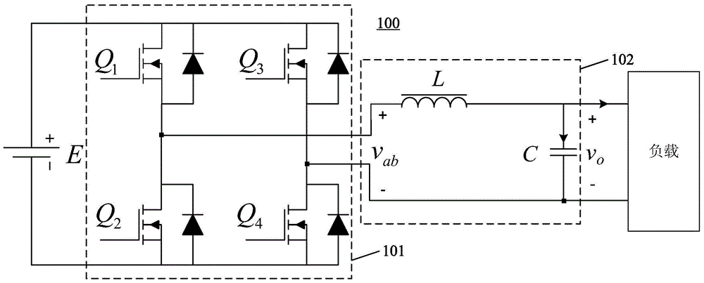
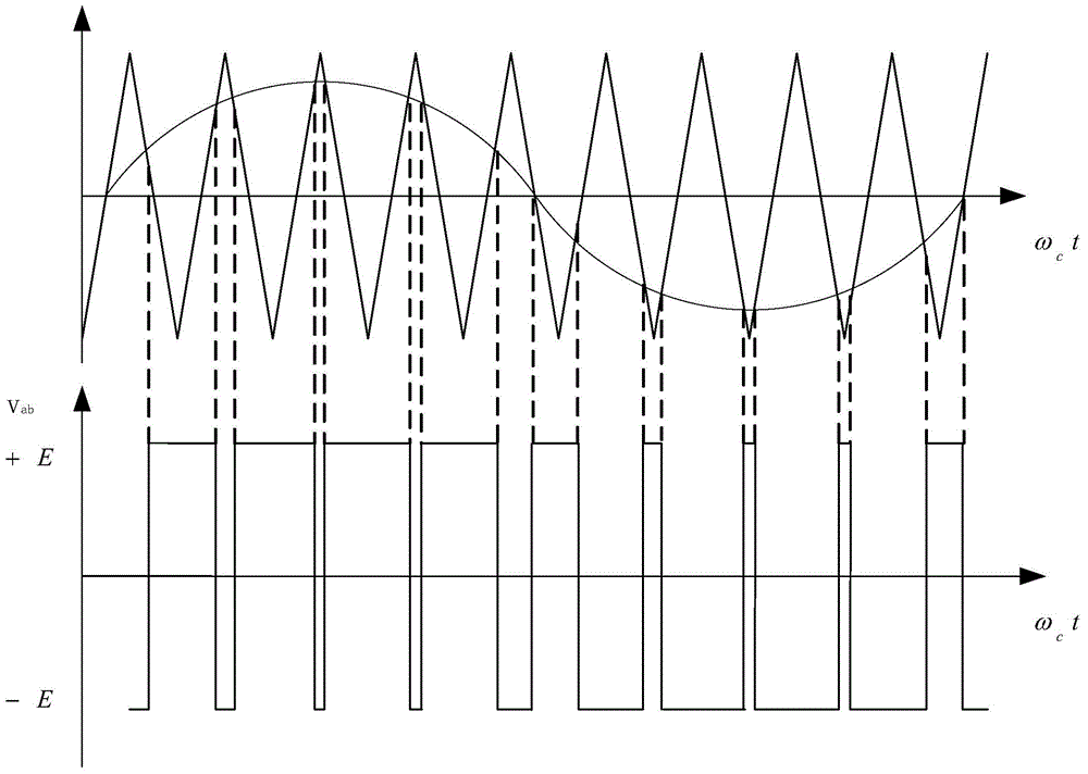
But the problem is that the four full-bridge switching tubes Q1~Q4 of the full-bridge bipolar SPWM work at high frequency, the switching loss of each full-bridge switching tube is relatively large, there are large switching harmonics, and the electromagnetic interference is large.
But the main problem is: the output voltage v of the full bridge circuit introduced by the output filter inductance L and filter capacitor C and load changes ab and the output voltage of the inverter v o Phase change, the phase change introduced by the closed-loop control (PID), makes the modulation wave and the output voltage have a phase difference, and the output voltage / current has zero-crossing distortion

Method used


Image

  • SPWM method of single-phase full bridge inverter
  • SPWM method of single-phase full bridge inverter
  • SPWM method of single-phase full bridge inverter

Examples


Embodiment Construction

[0027] The present invention will be further described below in conjunction with specific embodiment and accompanying drawing, set forth more details in the following description so as to fully understand the present invention, but the present invention can obviously be implemented in many other ways different from this description, Those skilled in the art can make similar promotions and deductions based on actual application situations without violating the connotation of the present invention, so the content of this specific embodiment should not limit the protection scope of the present invention.

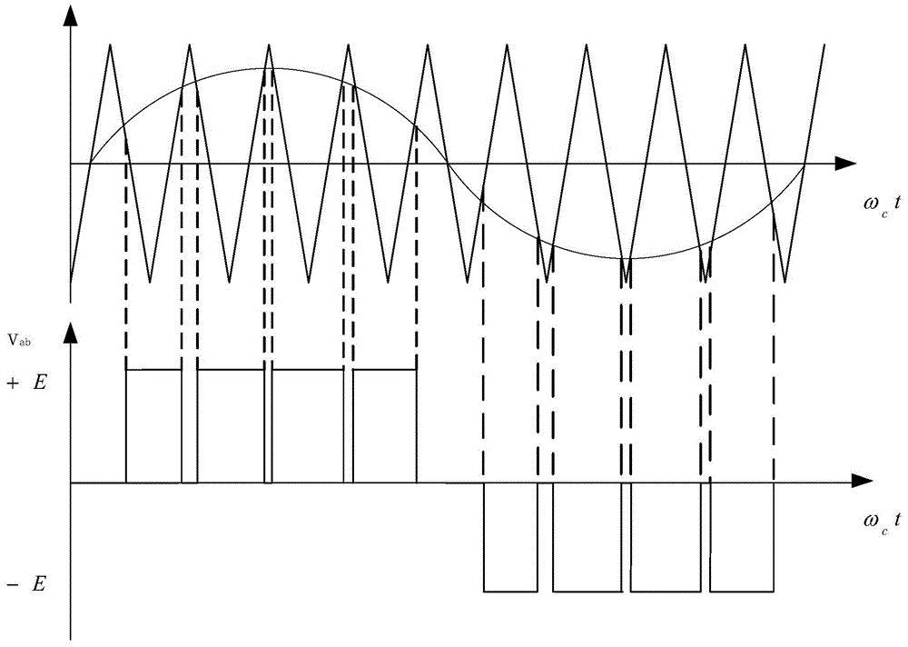
[0028] Figure 4 It is a schematic flow chart of the SPWM modulation method of the single-phase full-bridge inverter of an embodiment of the present invention; Figure 5 It is a waveform diagram of SPWM modulation of a single-phase full-bridge inverter according to an embodiment of the present invention. In addition, in the following description of the present invention, it is...


PUM


Abstract

The invention provides an SPWM method of a single-phase full bridge inverter. The single-phase full bridge inverter comprises a main circuit and a control system. The SPWM method comprises the following steps: (A) detecting whether a modulation voltage is in phase with an output voltage of the single-phase full bridge inverter by virtue of the control system, when the modulation voltage is not in phase with the output voltage, carrying out a step (B), and when the modulation voltage is in phase with the output voltage, carrying out a step (C); (B) starting a bipolar SPWM modulation manner by virtue of the control system; (C) starting a unipolar SPWM modulation manner by virtue of the control system; (D) returning to the step (A), and carrying out looping execution. The SPWM method has the beneficial effects that the advantage that the zero-crossing distortion does not exists in the bipolar modulation manner and the advantage of low consumption of the unipolar modulation manner are combined, namely, the inverter works in the bipolar modulation manner in a zero-crossing section of the output voltage and works in the unipolar modulation manner in other sections, the advantages of the two modulation manners are integrated, and the disadvantages of the two modulation manners are abandoned.

Description

technical field [0001] The invention relates to the technical field of power conversion equipment, in particular, the invention relates to a SPWM modulation method of a single-phase full-bridge inverter. Background technique [0002] The single-phase full-bridge voltage-type SPWM inverter is an inverter that controls the on and off of the power switching device by the switch control signal generated by the sinusoidal pulse width modulation (SPWM). [0003] figure 1 It is a schematic circuit diagram of a main circuit of a single-phase full-bridge inverter in the prior art. like figure 1 As shown, the main circuit of the single-phase full-bridge inverter 100 includes a full-bridge circuit 101 and a low-pass filter circuit 102 . An input terminal of the full bridge circuit 101 is connected to a DC bus voltage E, and an output terminal thereof is connected to a load through the low-pass filter circuit 102 . The low-pass filter circuit 102 includes a filter inductor L and a f...

Claims


Application Information

Patent Timeline
IPC IPC(8): H02M7/5395
Inventor 罗宇浩祁飚杰
Owner ALTENERGY POWER SYST
Learn More