
A zno/vo 2 Composite thermal phase change material and preparation method thereof

A phase change material, thermal phase change technology, applied in the growth of polycrystalline materials, chemical instruments and methods, nanotechnology for materials and surface science, etc., can solve the problem of temperature-controlled devices without metal-semiconductor phase change The process is difficult to deal with, and it is difficult to solve the problems of nano-optical electronic devices, so as to achieve the effect of rich morphology, controllable morphology and simple process.

Active Publication Date: 2016-06-08
南京浦裕投资有限公司
View PDF5 Cites 2 Cited by
  • Summary
  • Abstract
  • Description
  • Claims
  • Application Information

AI Technical Summary

Problems solved by technology

At present, hydrothermal method and vapor deposition method are used to prepare VO 2 The main method of nanostructure, VO prepared by hydrothermal method 2 Although the nanostructures are rich in morphology, they have many impurities, irregular arrangement, and no metal-semiconductor phase transition characteristics. 2 It must also undergo high temperature thermal conversion
Vapor deposition can directly synthesize phase-change VO 2 nanostructures, but due to VO 2 The growth of nanostructures is not a typical gasification-nucleation-growth VLS mode, but a melting growth process involving many intermediate phases, so it often requires a high temperature environment (800 ° C ~ 1100 ° C), and the obtained products often have morphology Single (mostly one-dimensional linear nanostructures), growing parallel to the substrate surface, difficult to peel off from the substrate and mass-produced, causing difficulties for the subsequent processing of subsequent temperature-controlled devices, and it is also difficult to be applied to nano Optoelectronics go up

Method used


Image

  • A zno/vo  <sub>2</sub> Composite thermal phase change material and preparation method thereof
  • A zno/vo  <sub>2</sub> Composite thermal phase change material and preparation method thereof

Examples


Embodiment 1

[0023] The concrete steps of this embodiment are as follows:

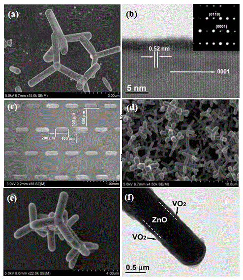
[0024] In the first step, ZnO powder and graphite powder are mixed and stirred at a mass ratio of 1:1, loaded into a quartz boat and placed in the center of the horizontal quartz tube furnace tube, and then the alumina substrate is placed on the horizontal tube In a type furnace, the substrate is covered with a stainless steel template, and the template is provided with holes arranged in a periodic distribution. A preferred periodic distribution of the holes is arranged in a matrix. The row spacing of the holes is 600 μm, and the column spacing is The hole is a rounded rectangular hole with a length of 400 μm and a width of 150 μm, so that a patterned template is formed, and the distance between the quartz boat and the template is 11 cm.

[0025] In the second step, the temperature at the center of the furnace tube was raised to 300°C at a rate of 10°C / min, kept for 20 minutes, and then naturally cooled to 180°C. ...

Embodiment 2

[0032] The steps of the present embodiment are the same as the steps of the above-mentioned embodiment 1, and the difference is the variation of some control quantities in the specific steps, as follows:

[0033] In the first step: a. the distance between the substrate and the quartz boat is controlled at 8cm;

[0034] In the second step: a. the temperature at the center of the furnace tube is raised to 290° C. at a rate of 8° C. / min and maintained for 25 minutes;

[0035] b. Nitrogen as a carrier gas is used to bring the central temperature of the furnace chamber to 475°C at a heating rate of 10°C / min and keep it for 35 minutes.

[0036] In the third step: a. The temperature in the vanadyl acetylacetonate storage area is controlled at 200°C; the purity is 99.999%;

[0037] b. Oxygen and nitrogen with a purity of 99.999% and a volume ratio of 8:92 are mixed to form a carrier gas, and the carrier gas is passed into the chemical vapor deposition system at a flow rate of 40ccm, ...

Embodiment 3

[0039] The steps of the present embodiment are the same as the steps of the above-mentioned embodiment 1, and the difference is the variation of some control quantities in the specific steps, as follows:

[0040] In the first step: a. the distance between the substrate and the quartz boat is controlled at 15cm;

[0041] In the second step: a. the temperature at the center of the furnace tube is raised to 310° C. at a rate of 12° C. / min and maintained for 15 minutes;

[0042] b. Feed nitrogen gas with purity and flow rate of 98.5% to 99.999% and 520 sccm respectively as carrier gas, and raise the temperature of the center of the furnace chamber to 485° C. at a heating rate of 20° C. / min and keep it for 45 minutes.

[0043] In the third step: a. The temperature in the vanadyl acetylacetonate placement area is controlled at 200°C;

[0044] b. Oxygen and nitrogen with a purity of 99.999% and a volume ratio of 11:89 are mixed to form a carrier gas, and the carrier gas is passed in...


PUM

PropertyMeasurementUnit
lengthaaaaaaaaaa
widthaaaaaaaaaa
diameteraaaaaaaaaa

Abstract

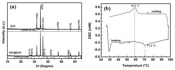
The present invention relates to a kind of ZnO / VO 2 Composite nanomaterials and methods for their preparation. The material is attached on the alumina substrate and has units arranged in a periodic arrangement, and each unit is made of coated VO 2 The single crystal nanostructure composed of several ZnO tetragonal rods in the polycrystalline shell layer has a phase transition temperature of 71.2ºC and has reversible metal-insulator phase transition characteristics. The preparation of the material firstly uses ZnO powder and graphite powder as raw materials to synthesize single crystal tetragonal rod-shaped ZnO nanomaterials by thermal evaporation; 2 ) as the raw material, and deposited polycrystalline VO 2 thin film; finally remove the template to get patterned VO 2 / ZnO composite phase change material. The advantage is that the VO produced by this method 2 The nanostructure is rich in morphology, with VO 2 The metal-semiconductor phase transition characteristics of ZnO combined with the characteristics of wide bandgap semiconductor of ZnO have a good application prospect.

Description

technical field [0001] The invention relates to the technical fields of semiconductor materials, optoelectronic materials, phase change materials and devices, in particular to a ZnO / VO grown on an alumina substrate and periodically arranged 2 Composite nanomaterials and methods for their preparation. Background technique [0002] Monoclinic VO 2 It is a thermally induced phase change material. When the temperature is lower than 68°C, VO 2 It is in a semiconducting state with a monoclinic crystal structure; when the temperature is higher than 68°C, VO 2 Transforms into a metallic state with a tetragonal rutile structure and a very rapid phase transition. Accompanied by the change of the crystal structure, the resistivity, magnetic susceptibility, light transmittance and reflectivity all have sudden changes. These properties make VO 2 It has become a photoelectric conversion material, optical storage, laser protection and smart window material with broad application prosp...

Claims


Application Information

Patent Timeline
Patent Type & Authority Patents(China)
IPC IPC(8): C30B29/16C30B29/62C30B28/14B82Y40/00B82Y30/00
Inventor 尹海宏王志亮宋长青陈云施敏张雪锋朱友华
Owner 南京浦裕投资有限公司
Learn More