A rotary regenerative air preheater

An air preheater, regenerative technology, applied in lighting and heating equipment, combustion methods, indirect carbon dioxide emission reduction, etc. Pressure, temperature fluctuations and other problems, to achieve the effect of long service life, large bearing capacity and low running resistance

Active Publication Date: 2016-02-24
YUEYANG ZHONGDING THERMAL ELECTROMAGNETIC TECH CO LTD +1
View PDF7 Cites 0 Cited by
  • Summary
  • Abstract
  • Description
  • Claims
  • Application Information

AI Technical Summary

Problems solved by technology

[0004] Most of the existing air preheaters have some deficiencies. For example, the switchable regenerative condensing air preheater includes two or more regenerators. The regenerators are filled with heat storage media, and the flue gas temperature drops to The acid is discharged below the dew point, but a three-way valve is often used to switch the heat storage and heat release process of a single regenerator to recover the heat energy of the flue gas. The switching process will cause fluctuations in combustion pressure and temperature
For example, the rotary preheater adopts rotary heat transfer to store and cool the high-temperature flue gas at 1200°C to below 200°C and discharge it, but it does not consider how to deal with the formed acidic condensate when the exhaust gas temperature drops below the dew point. , so in actual operation, the exhaust gas temperature still needs to be controlled above the dew point corrosion temperature to avoid the impact of acid condensate on the device and the environment, and at the same time, the latent heat of vaporization in the flue gas is not recovered
For example, other equipment proposes to neutralize the acidic condensate formed after low-temperature condensation with alkaline substances, but the heavy metal ions in the condensate are not treated but are discharged together with the condensate, forming secondary pollution

Method used


Image

  • A rotary regenerative air preheater
  • A rotary regenerative air preheater

Examples


specific Embodiment

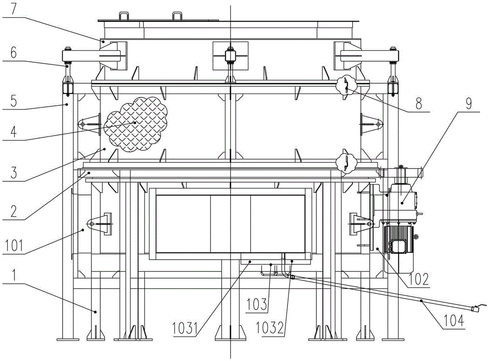
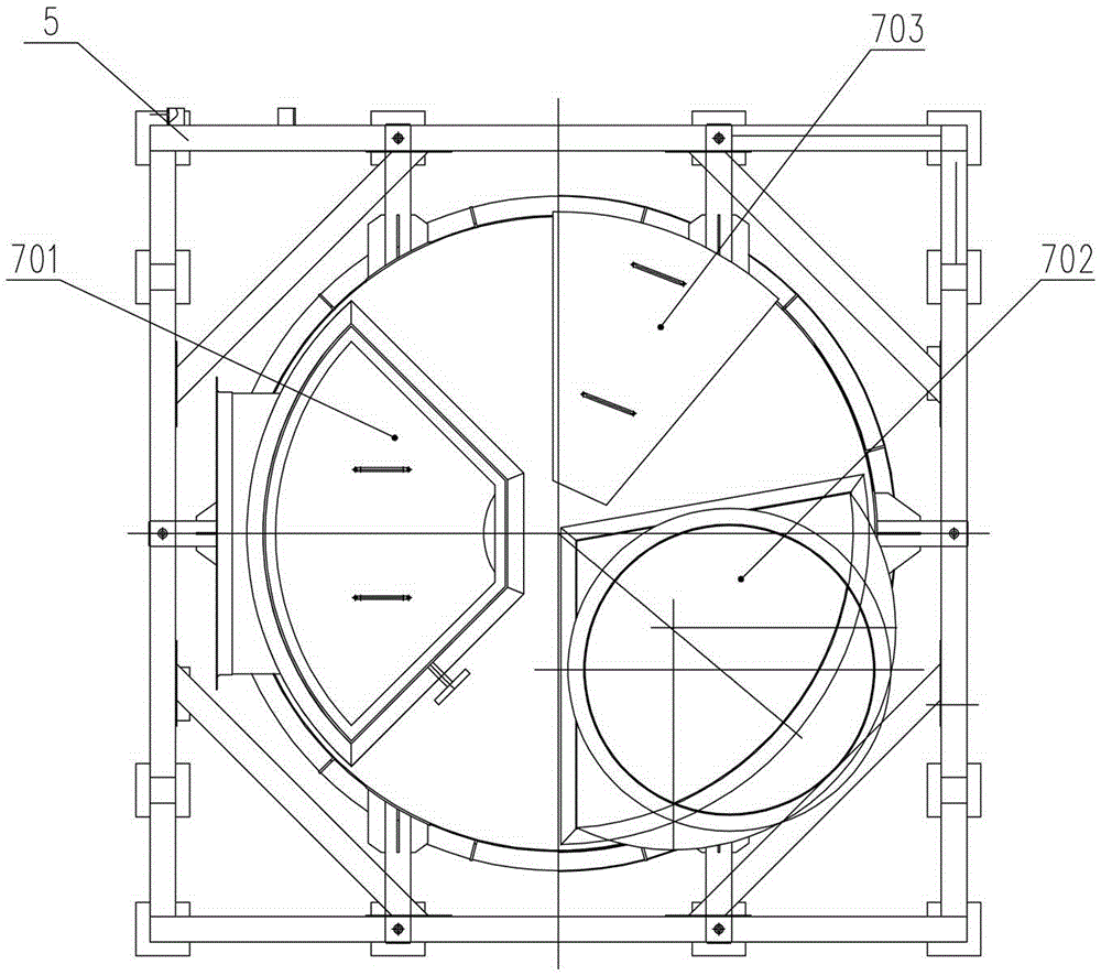
[0019] Such as figure 1 , 2 As shown, the present invention comprises a base 1, a slewing bearing 2, a gyrator 3, a heat storage body 4, a support frame 5, an adjustment device 6, a top cover 7, a seal 8, a reducer 9 and an insulating material; on the base 1 The lower air inlet 101 and the lower flue gas outlet 102 are provided; the top cover 7 is provided with an upper air inlet 701 , an upper flue gas inlet 702 and a maintenance hole 703 .

[0020] Such as figure 1 As shown, the interior of the base 1 is divided into two independent sections of air and smoke, the cold air is input from the lower air inlet 101 , and the cold smoke is discharged from the lower smoke outlet 102 . At the bottom of the base 1, a condensate collection and neutralization device 103 is installed in the flue gas chamber. The condensate collection and neutralization device 103 is composed of a mixed sedimentation chamber 1031 and a heavy metal treatment chamber 1032. The treated condensate is discha...


PUM


Abstract

The invention relates to a heat accumulating type slewing air preheater which comprises an upper air chamber, a lower air chamber and a middle slewing heat accumulating device. The slewing heat accumulating device comprises a slewing bearing, a speed reducer and a slewing body, wherein the slewing bearing is arranged at the top of the lower air chamber, the speed reducer is arranged on one side of the slewing bearing and drives the slewing bearing to rotate, and the slewing body is arranged on the slewing bearing and rotates along with the slewing bearing. A liquor condensate collection and neutralization system is arranged at the bottom of a cold smoke chamber of the lower air chamber and comprises a mixed precipitation chamber and a heavy metal processing chamber, wherein limestone alkaline particles are arranged in the mixed precipitation chamber, the heavy metal processing chamber is connected with a discharging pipe, and processed liquor condensate is discharged out through the discharging pipe. The slewing bearing drives the slewing body and a heat accumulating body to rotate to complete heat exchange between high-temperature smoke and cold air, pollutants such as acid liquid containing nitration and sulfide and produced by condensation of low-temperature smoke can be collected and neutralized through the liquor condensate collection and neutralization system, and therefore, air pollution caused by smoke discharged out of a heating furnace is reduced.

Description

technical field [0001] The invention relates to air preheating equipment, in particular to a rotary regenerative air preheater suitable for reclaiming high-efficiency flue gas discharged from combustion equipment to preheat cold air in the petrochemical industry. Background technique [0002] The heating furnace is a combustion equipment widely used in the petroleum, chemical, and chemical fiber industries. It generates high-temperature flue gas by burning fuel oil or fuel gas, and heats the medium in the furnace tube. Due to the sulfur, nitrogen and other substances contained in the fuel and air, acid gases are generated after combustion. In order to prevent the acid gases in the flue gas from corroding the equipment, the exhaust gas temperature of the heating furnace is controlled above the dew point corrosion temperature, and the exhaust gas temperature is generally 130 ℃~200℃, the thermal efficiency is usually lower than 90%, part of the physical sensible heat in the flu...

Claims


Application Information

Patent Timeline
Patent Type & Authority Patents(China)
IPC IPC(8): F23L15/00
CPCY02E20/34
Inventor 游述怀聂勇吴时骅
Owner YUEYANG ZHONGDING THERMAL ELECTROMAGNETIC TECH CO LTD
Why Eureka
Try Eureka