Solar cell slice and fabrication method thereof

A technology of solar cells and back electric field, applied in the field of solar cells, can solve the problems that the fine density of the grid lines of the silver seed layer is not easy to meet the design requirements, the photoelectric conversion efficiency of the cells is decreased, the short-circuit current of the cells is decreased, etc., and the short-circuit current and the filling factor can be achieved. Increase, photoelectric conversion efficiency improvement, series resistance reduction effect

Inactive Publication Date: 2014-10-01
BYD CO LTD
View PDF3 Cites 6 Cited by
  • Summary
  • Abstract
  • Description
  • Claims
  • Application Information

AI Technical Summary

Problems solved by technology

However, there are still many problems in the preparation and silk screen printing of the existing silver seed layer, which have affected its practical application. If the width increases too much, the shading area increases, causing the short-circuit current of the battery to decrease
[0004] At present, there are also methods to further reduce the cost, and the process of electroplating pure silver is improved to electroplating pure copper process, but in these processes, silver seed layer is formed by printing silver conductive paste, and the conductive paste contains solvent and organic binder. During the sintering process, solvents and organic binders are volatile when heated, which will leave tiny holes in the sintering residue. During the subsequent use of the battery, copper atoms may pass through the holes and come into contact with the silicon substrate, resulting in battery failure. The photoelectric conversion efficiency drops sharply, which affects the performance of the cell

Method used


Image

  • Solar cell slice and fabrication method thereof

Examples


Embodiment 1

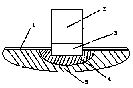
[0029] (1) The specifications of the polysilicon wafer used are: 156×156mm. The thickness is 200 μm (before etching), and the thickness before printing is 180 μm. Texturize the silicon wafer, make PN junction, and coat silicon nitride anti-reflection film by PECVD method. First use screen printing back silver paste (PV505 silver paste from Dupont Company), dry it, and print the back field aluminum paste (Taiwan Shuohe Technology 108C aluminum paste) on the remaining part of the back light surface after printing the back silver paste. After drying, After sintering in a tunnel furnace, a silicon substrate sheet with a silver back electrode and an aluminum back field is obtained.

[0030] as attached figure 1 shown.

[0031] (2) Preparation of heavily doped selective emitter region 4

[0032] The front electrode is designed to include three main grids, and a layer of phosphoric acid solution with a concentration of 2.0wt% is spin-coated on the silicon base sheet 5 (the front ...

Embodiment 2

[0040] Solar cell sample S2 was prepared in the same manner as in Example 1, except that the evaporation time in step (3) was 8 minutes, and the obtained sub-grid metal titanium layer had a height of 0.20-0.40 μm and a width of 8.0- 10 μm. The total height of the sub-grid lines of the front electrodes obtained from the test is 9.0-12 μm, and the total width is 18-23 μm.

Embodiment 3

[0042] Solar cell sample S3 was prepared by the same method and steps as in Example 1, except that the evaporation time in step (3) was 30 minutes, and the height of the titanium layer of the auxiliary grid line was 1.4-1.6 μm, and the width was 15-15 μm. 18 μm. The total height of the sub-grid lines of the front electrodes obtained from the test is 12-15 μm, and the total width is 25-30 μm.


PUM

PropertyMeasurementUnit
heightaaaaaaaaaa
widthaaaaaaaaaa
heightaaaaaaaaaa

Abstract

The invention provides a solar cell slice and a fabrication method thereof. The solar cell slice comprises a silicon substrate slice, a positive-surface electrode on the front surface of the silicon substrate slice, a back electric field on the back surface of the silicon substrate and a back electrode electrically communicated with the back electric field, wherein the front surface of the silicon substrate slice comprises a non-antireflection film region, and the positive-surface electrode comprises a metal titanium layer arranged on the surface of the non-antireflection film region and a conductive metal layer arranged on the surface of the metal titanium layer. The positive-surface electrode is high in fine density, line broken is difficult to happen, the solar cell slice is difficult to strip and fall off, the resistance when the cells are connected in series is low, high fill factor is achieved, the photoelectric conversion efficiency of the cell is high, and the cost is low.

Description

technical field [0001] The invention relates to the field of solar cells, more specifically, the invention relates to a solar cell sheet and a preparation method thereof. Background technique [0002] As a kind of green energy, solar energy has attracted more and more attention due to its advantages of inexhaustibility, no pollution, and no limitation of geographical resources. Existing silicon-based solar cells generally prepare electrodes and back field by printing conductive paste containing conductive metal powder, glass powder and organic vehicle on a silicon substrate, drying and firing. The back electrode of the solar cell silicon substrate is generally the positive electrode, and the coated conductive paste is usually the back silver paste; the back surface is generally coated with an aluminum-containing conductive paste, which forms an aluminum back field after sintering, which can significantly increase the open circuit voltage of the battery and photoelectric con...

Claims


Application Information

Patent Timeline
Patent Type & Authority Applications(China)
IPC IPC(8): H01L31/0224H01L31/18
CPCH01L31/02168H01L31/022433H01L31/1804Y02E10/547Y02P70/50
Inventor 谭伟华姜占锋何龙
Owner BYD CO LTD
Why Eureka
Try Eureka