Distributed optical fiber temperature sensor and method for removing nonlinear error of same

A technology of temperature sensor and distributed optical fiber, applied in the field of optical fiber temperature sensor and elimination of nonlinear error of the sensor, distributed optical fiber temperature sensor and elimination of nonlinear error of the sensor, can solve the problems of large measurement accuracy of the system, and achieve response The effect of fast, high measurement accuracy and simple operation

Active Publication Date: 2014-10-15
KINGSHORE NEW RESOURCES ELECTRIC JIANGSU
View PDF10 Cites 19 Cited by
  • Summary
  • Abstract
  • Description
  • Claims
  • Application Information

AI Technical Summary

Problems solved by technology

In particular, as the measurement distance increases, the loss diffe

Method used


Image

  • Distributed optical fiber temperature sensor and method for removing nonlinear error of same
  • Distributed optical fiber temperature sensor and method for removing nonlinear error of same
  • Distributed optical fiber temperature sensor and method for removing nonlinear error of same

Examples


Embodiment 1

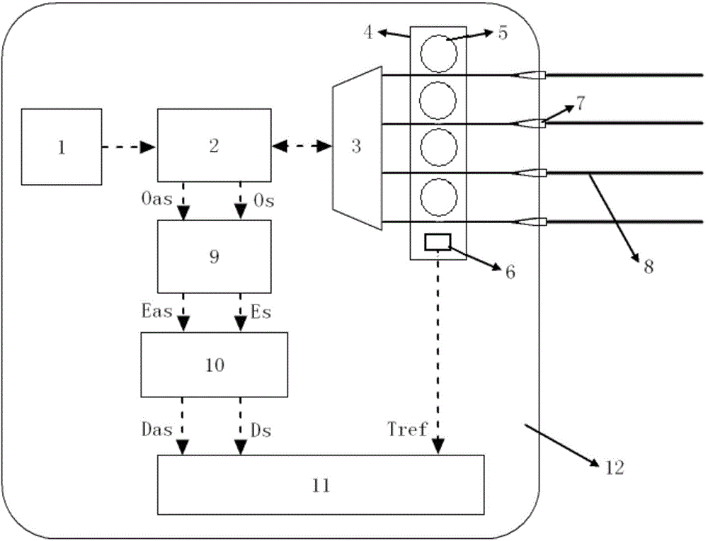
[0055] This embodiment provides a distributed optical fiber temperature sensor with a structure such as figure 1 As shown, it mainly includes the casing 12 and the optical fiber laser of the MOPA structure which is arranged in the casing 12 and connected sequentially with a wavelength of 1550.12nm, a pulse width of 10ns, a peak power of 15W, and a repetition period of 152us as the pulse laser source 1. , a wavelength division multiplexer 2 and an optical switch 3, an optical fiber box 4 made of aluminum alloy is also connected to the optical switch 3, a reference optical fiber ring 5 with a length of 20m and a winding diameter of 15m is arranged in the optical fiber box 4, the optical fiber box 4 is also provided with a dedicated temperature measuring chip DS18B20 integrated with the reference optical fiber ring 5 as the temperature probe 6, and the tail end of the reference optical fiber ring 5 is connected to the external 50 / 125um multimode fiber optic connection;

[0056...

Embodiment 2

[0059] This embodiment provides a method for eliminating the nonlinear error of the distributed optical fiber temperature sensor in Embodiment 1, which uses the method of compensating for the loss difference in sections to eliminate the difference in Raman Stokes and anti-Stokes optical loss. The nonlinear error of , the specific steps are as follows:

[0060] (1) Utilize photodetection module 9 in the distributed temperature sensor to detect the power of Stokes light and anti-Stokes light and record it, and the expressions of Stokes light and anti-Stokes light power are as follows:

[0061] P s = P 0 · K s · S b · v s 4 · R s ( T ) · e ...


PUM

PropertyMeasurementUnit
Center wavelengthaaaaaaaaaa
Pulse widthaaaaaaaaaa
Peak poweraaaaaaaaaa

Abstract

The invention discloses a distributed optical fiber temperature sensor which mainly comprises a machine casing and a pulse laser source, a wavelength division multiplexer and an optical switch which are arranged in the machine casing. The optical switch is further connected with an optical fiber box, a reference optical fiber ring is arranged in the optical fiber box, a temperature probe is further arranged on the optical fiber box, and the tail end of the optical fiber ring is connected with an external sensing optical fiber through an optical terminal arranged on the machine casing. The wavelength division multiplexer is further sequentially connected with a photoelectric detection module, a high speed collection card and an industrial personal computer board card. The sensor is low in cost, simple in structure, good in signal to noise ratio, good in stability, reliable and high in temperature resolution. A method for removing a nonlinear error of the distributed optical fiber temperature sensor by utilizing a subsection loss difference compensation method to remove the nonlinear error caused by Raman Stokes and anti-Strokes optical loss difference is further provided. By means of the method, a temperature curve demodulated by the system accords with the actual condition, and temperature measuring accuracy and reliability of the system are improved.

Description

technical field [0001] The invention discloses an optical fiber temperature sensor and a method for eliminating the nonlinear error of the sensor, in particular to a distributed optical fiber temperature sensor and a method for eliminating the nonlinear error of the sensor, belonging to the field of optical fiber sensing. Background technique [0002] Since J.P.Dakin and others first successfully realized the distributed temperature measurement technology based on Raman scattering in 1985, people have carried out extensive research on various technologies for realizing distributed optical fiber temperature sensing. Sensing technology has been the most widely used in practice. Compared with traditional sensors, distributed optical fiber temperature sensors have many excellent advantages: using optical fiber itself as the sensing medium, temperature information of thousands of points distributed along the optical fiber can be obtained in one measurement, which realizes continu...

Claims


Application Information

Patent Timeline
IPC IPC(8): G01K11/32G01K11/324
Inventor 周金龙朱冬宏田群
Owner KINGSHORE NEW RESOURCES ELECTRIC JIANGSU
Why Eureka
Try Eureka