Blind valve element of G-type electromagnetic directional valve and manufacturing method

An electromagnetic reversing valve and the technology of the manufacturing method are applied in the direction of sliding valves, valve devices, manufacturing tools, etc., which can solve the problems of low yield rate, metal corrosion-prone internal energy, low hardness and elastic modulus, etc., and achieve pressure resistance The effect of improving and reducing the difficulty of manufacturing process

Active Publication Date: 2014-10-22
GUANGDONG HUAYE POWER TECH
View PDF5 Cites 0 Cited by
  • Summary
  • Abstract
  • Description
  • Claims
  • Application Information

AI Technical Summary

Problems solved by technology

[0004] The G-type electromagnetic reversing valve commonly used now uses a metal blind valve core, but: 1. Because the metal material itself has obvious thermal expansion and contraction properties, relatively low hardness and elastic modulus, a small amount of heat can be removed during fine processing In addition to deformation, there will be traces of residual stress in metal materials due to its cold plasticity. This type of stress can make the size of the metal workpiece unstable, make the metal more prone to corrosion, increase its internal energy, and make the crystal lattice in an unstable state, etc., so In the production process of the manufacturer, the yield is very low, only about 50%
2. If figure 1 As shown, there is a blind hole 12 inside the blind spool 1. When using metal materials to make the blind spool 1, a welding process is also used to make the blind hole 12, as figure 1 Middle 11 is the welding place, which makes the processing relatively complicated, and the welding process increases the difficulty of controlling the metal to release the residual internal stress. The blind valve core and valve body have high requirements for the matching size and sealing parts, especially in high pressure and ultra-high pressure. Problems in the hydraulic system are even more prominent

Method used


Image

  • Blind valve element of G-type electromagnetic directional valve and manufacturing method
  • Blind valve element of G-type electromagnetic directional valve and manufacturing method
  • Blind valve element of G-type electromagnetic directional valve and manufacturing method

Examples


Embodiment

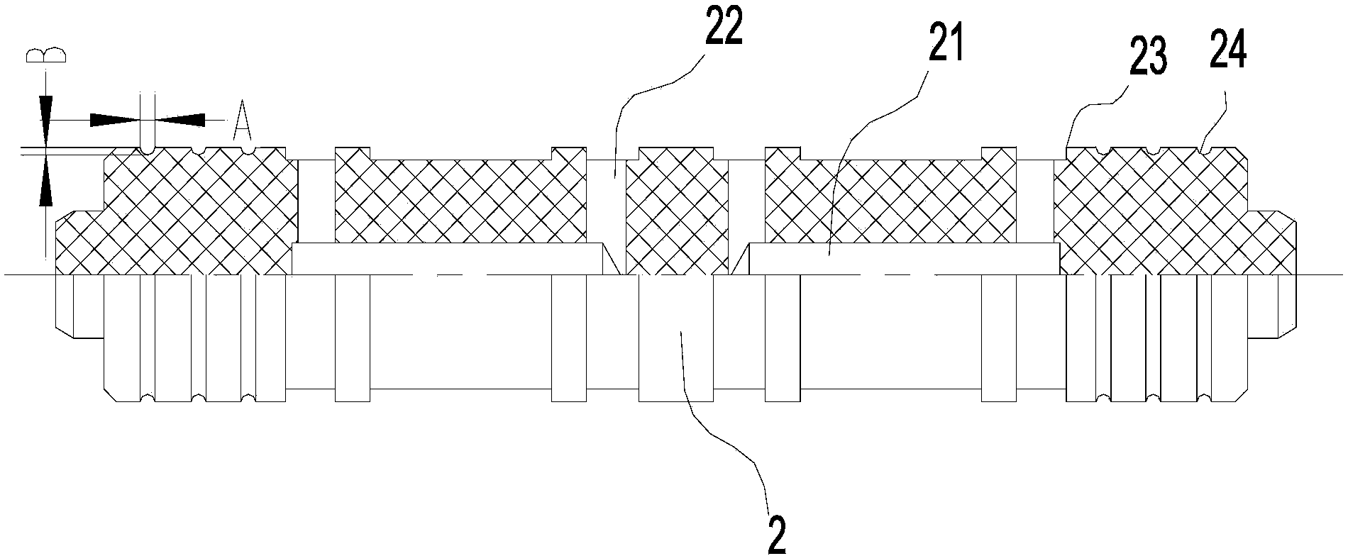
[0030] This embodiment provides a blind spool for G-type electromagnetic reversing valve, please refer to figure 2 , the blind spool 2 has an integral structure, and the blind hole 21 is processed through core bone making and core removal processes without welding.

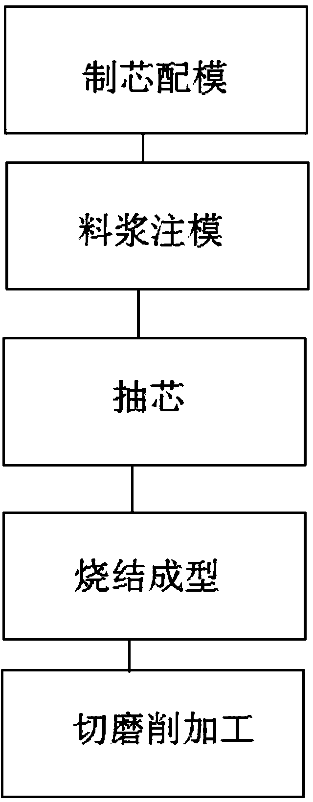
[0031] Specifically, please refer to image 3 , the manufacturing method of the blind spool comprises:

[0032] Core making and mold matching: set the mold, and the core bone is pre-embedded in the mold for the position of the blind hole;

[0033] Slurry injection molding: inject the slurry of special pottery raw materials into the cavity of the mold, and form the blind valve core blank;

[0034] Core pulling: remove the core bone in the blind valve core blank;

[0035] Sintering molding: sintering the blind valve core blank;

[0036] Cutting and grinding: Cutting and grinding the sintered blind valve core blank to make products.

[0037] Specifically, in the step of core making and mold matching, the mold c...


PUM


Abstract

The invention discloses a blind valve element of a G-type electromagnetic directional valve and a manufacturing method. The blind valve element is formed by integrally sintering, and a blind hole is formed by manufacturing a core rod and removing a core. Compared with a metal blind valve element, the blind hole can be formed without welding, the technological difficulty of manufacturing the blind valve element can be lowered, the blind valve element manufactured through the method is not expanded basically below 120 DEG C, the abrasion resistance, the hardness, the density and the pressure resistance of the blind valve element are greatly improved, the service life of the blind valve element is prolonged, the blind valve element is made to be more stable, the demands for ordinary pressure and intermediate pressure can be met, and the demands of high pressure hydraulic systems, ultrahigh pressure hydraulic systems and ultra-ultrahigh pressure hydraulic systems can be met.

Description

technical field [0001] The application relates to a blind valve core of a G-type electromagnetic reversing valve and a manufacturing method thereof. Background technique [0002] Electromagnetic reversing valve is an industrial device controlled by electromagnetic force. It is an automatic basic component used to control the flow direction of fluid. It is often used to adjust the flow direction of fluid medium in industrial control systems. The electromagnetic reversing valve controls the reversing or start-stop of hydraulic actuators (such as hydraulic rods and hydraulic motors) by changing the relative working position of the valve core in the valve body to connect or disconnect each oil port of the valve body. [0003] Solenoid directional valves are divided into spool valves, rotary valves and ball valves, and spool type solenoid directional valves are the most commonly used. The spool type electromagnetic reversing valve is divided into many types because of its differ...

Claims


Application Information

Patent Timeline
Patent Type & Authority Applications(China)
IPC IPC(8): B28B1/24B28B13/00C04B35/64F16K3/314
CPCB28B1/24B28B13/00C04B35/64F16K3/314
Inventor 李敏孙玉岗葛台代陈铭斌陈其永
Owner GUANGDONG HUAYE POWER TECH
Why Eureka
Try Eureka