Liquid metal ink-jet printing equipment and printing method

An inkjet printing equipment and liquid metal technology, applied in printing devices, printing, etc., can solve problems such as high environmental pollution, complex manufacturing procedures of integrated circuits or electronic devices, large material and energy consumption, and achieve energy consumption and material inefficiency Effects of low loss, reduced complexity and cost, and improved productivity

Inactive Publication Date: 2014-10-22
TECHNICAL INST OF PHYSICS & CHEMISTRY - CHINESE ACAD OF SCI
View PDF10 Cites 56 Cited by
  • Summary
  • Abstract
  • Description
  • Claims
  • Application Information

AI Technical Summary

Problems solved by technology

[0006] The object of the present invention is to provide a liquid metal inkjet printing equipment and printing method that can directly print circuits and electronic devices to solve the pro...

Method used


Image

  • Liquid metal ink-jet printing equipment and printing method
  • Liquid metal ink-jet printing equipment and printing method
  • Liquid metal ink-jet printing equipment and printing method

Examples


Embodiment 1

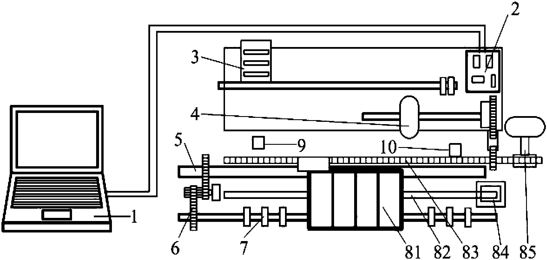
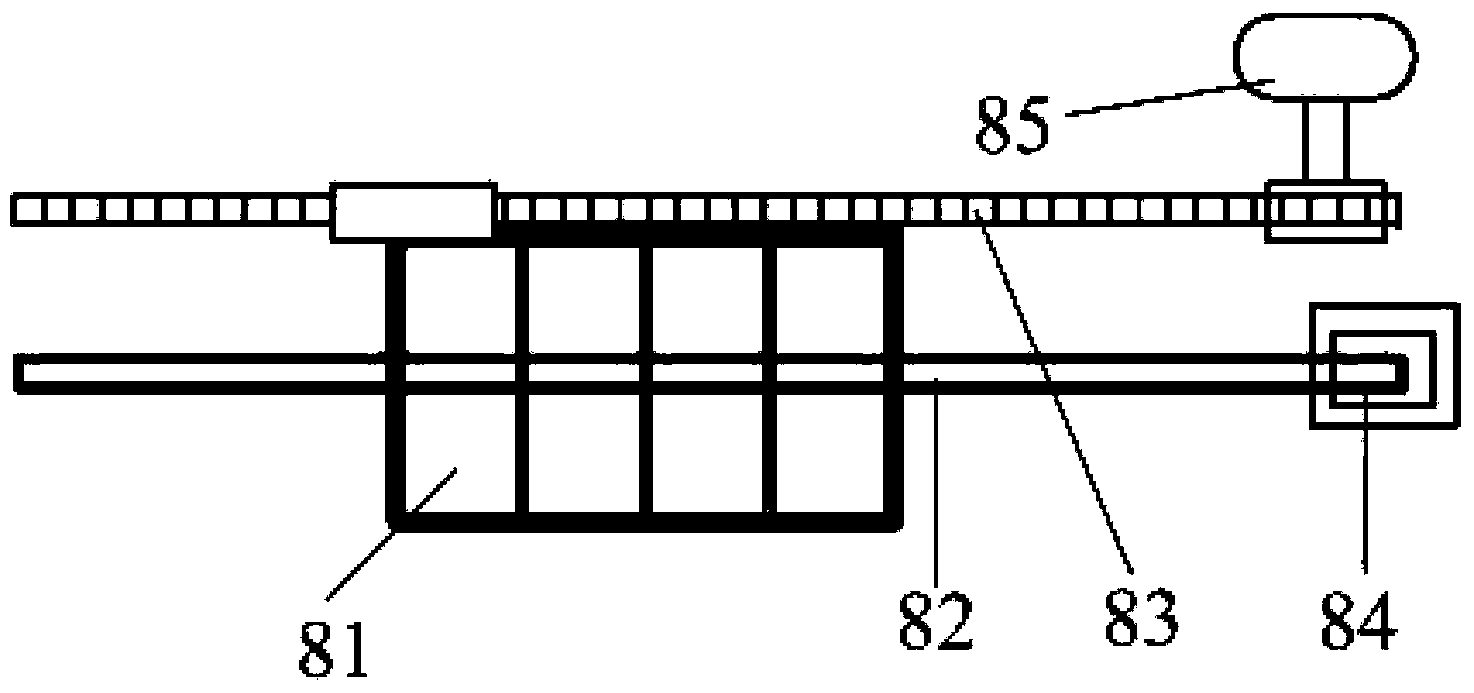
[0050] attached figure 1 It is a structural schematic diagram of the liquid metal micro piezoelectric printer of the present invention. The main structure of the printer includes: a computer 1 with built-in printing control software, a control circuit board 2 built in the liquid metal micro piezoelectric printer, a paper feeder 3, Platen roller 4 , paper feed roller 5 , gear set 6 , paper output roller 7 , carriage mechanism 8 , bottom end paper sensor 9 and carriage initial position sensor 10 . Among them, the control circuit board 2 is used to receive the printing control instruction from the computer 1, and control the paper feeder 3, paper pressing roller 4, paper feeding roller 5, gear set 6, paper output roller 7, initial Position sensor 9 carries out coordinated operation with word car mechanism. The paper feeder 3 and the platen roller 4 are used to guide and flatten the printing substrate. The paper feed roller 5 and the gear set 6 are used to make the paper feeder ...

Embodiment 2

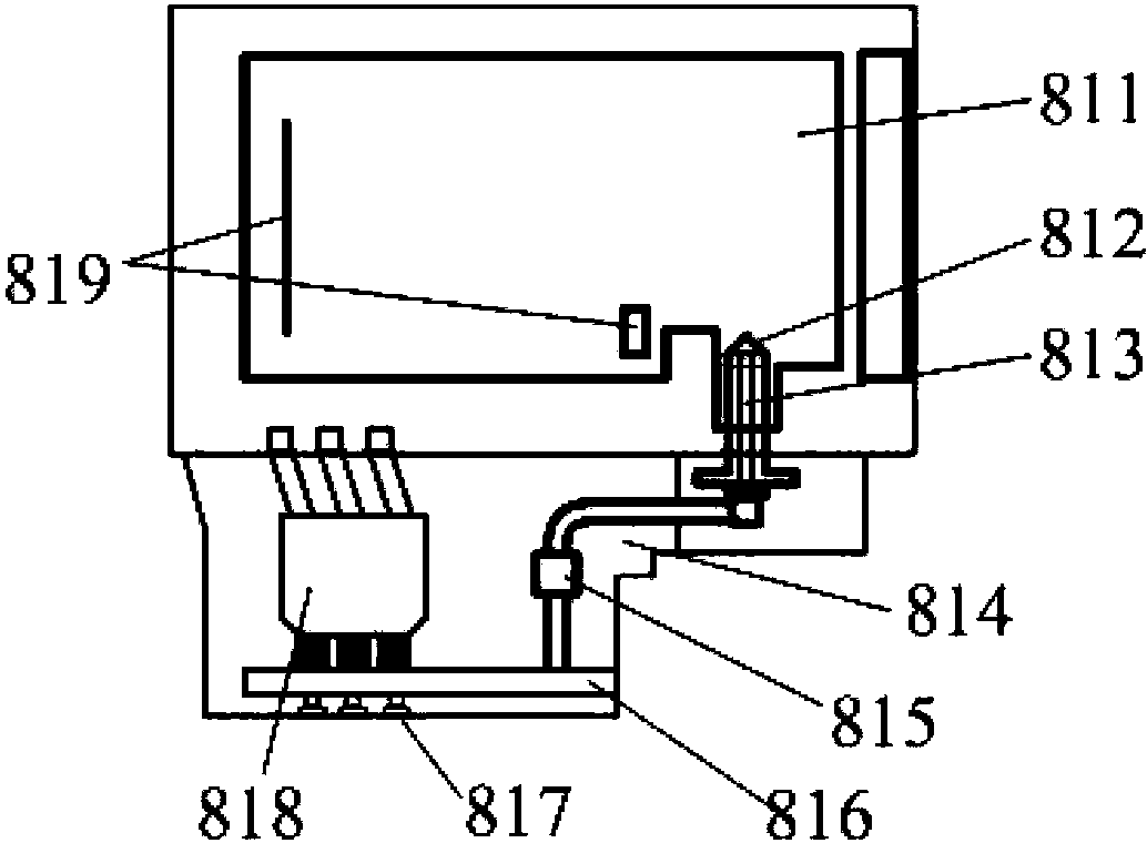
[0059] The only difference between this embodiment and Embodiment 1 is the electric control driving mode. In this embodiment, the injection of the ink at the nozzle is driven by an electromagnetic pump. Since liquid metal is a conductive fluid, it is easy to realize spraying under automatic control by using an electromagnetic pump, and its spraying speed depends on the current on the flow channel. Here, the ejection driving element is the electromagnetic pump 818 , and after it starts running, the liquid metal ink will be pushed to the nozzle by the electromagnetic force generated by the electromagnetic pump and ejected onto the printing substrate. Component 818 is an inkjet head drive device that adopts the working principle of metal liquid electromagnetic drive. When the control circuit board 2 sends a print command signal, the electromagnetic pump component 818 exerts a Lorentz electromagnetic force on its internal fluid, and then the ink stored in the ink chamber 814 The ...


PUM


Abstract

The invention provides a liquid metal ink-jet printing equipment. The liquid metal ink-jet printing equipment comprises a control circuit used for carrying integral control on the printing equipment, a liquid metal printing mechanism used for bearing an ink box and an electrical control nozzle and printing liquid metal oil ink on a base, a carriage mechanism which is used for bearing the liquid metal printing mechanism and moves according to an instruction of the control circuit, a paper conveying mechanism used for conveying a printing base of the printing equipment, and a state sensor used for detecting a work state of the printing equipment. According to the liquid metal ink-jet printing equipment and the printing method, problems of complex manufacturing process, large material and energy consumption and relatively serious environment pollution existing in an integrated circuit or an electronic device in the prior art are solved, and the relatively good technology effect is acquired.

Description

technical field [0001] The invention relates to the field of manufacturing printed circuits and printed electronic devices, in particular to a liquid metal inkjet printing device and a printing method. Background technique [0002] Microelectronic integrated circuit technology based on semiconductor monocrystalline silicon as substrate material has been developed for 50 years. The manufacture of modern silicon-based integrated circuits has become an extremely complex technical field, from the preparation of single crystal silicon sinking materials to the thin film deposition, photolithography, etching, packaging, etc. required to form transistors and interconnection lines on it. The process steps involved are relatively complicated. In recent years, some disadvantages of traditional integrated circuit technology have gradually been recognized, including high equipment cost, high energy consumption, high pollution, and high cleanliness requirements. The main reason is that ...

Claims


Application Information

Patent Timeline
IPC IPC(8): B41J29/393B41J2/015
Inventor 刘静郑义
Owner TECHNICAL INST OF PHYSICS & CHEMISTRY - CHINESE ACAD OF SCI
Why Eureka
Try Eureka