
Process method for recycling acetone from exhaust gas

A process method and acetone technology, which are applied in chemical instruments and methods, preparation of organic compounds, separation/purification of carbonyl compounds, etc., can solve the problems of high energy consumption, poor stability, and difficult separation of acetone recovery.

Inactive Publication Date: 2014-11-05
HEBEI UNIV OF TECH
View PDF6 Cites 0 Cited by
  • Summary
  • Abstract
  • Description
  • Claims
  • Application Information

AI Technical Summary

Problems solved by technology

However, there are many disadvantages in the process of recovering acetone by activated carbon fixed bed adsorption: (1) the operation of the activated carbon adsorption process is intermittent, and the stability is relatively poor; (2) the analysis process needs to consume a large amount of steam, and the heat utilization rate is low, making The cost is high; (3) If the analysis process is not complete, it may cause the activated carbon to catch fire, and there are certain safety hazards; (4) The material transportation and absorption processes are all operated in a gaseous state, and there is a risk of explosion
[0003] Although the recovery of acetone by the water absorption method in the original process is continuous, the process is stable, safe and reliable, the energy consumption of the recovery of acetone by the water absorption method is relatively large.
There are two main reasons why the energy consumption of acetone recovered by the water absorption method in the original process is large: one is that the dilute acetone formed after the absorption of trace acetone by water contains less acetone in the water, with a mass fraction of 3.5% to 4.2%. It directly enters the distillation tower for distillation, which causes a great load to the distillation tower; second, the recovery of acetone by the original process water absorption method is mostly operated under normal pressure, and the relative volatility between its components is small, and the separation is relatively difficult, requiring a large reflux flow rate. Separation requirements can be achieved with the same number of plates

Method used


Image

  • Process method for recycling acetone from exhaust gas

Examples


Embodiment 1

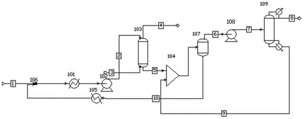
[0041] The acetone to-be-treated gas 3 containing about 1.79% mole fraction enters from the bottom of the absorption tower 103, and the feed temperature is 20°C. The gas 3 to be treated rises continuously in the absorption tower 103 and meets the condensed absorption water 2 entering from the top of the absorption tower 103 countercurrently. The condensed absorption water 2 enters the tower at a temperature of 10°C and sprays down from the top of the tower. After the trace amount of acetone is condensed and absorbed by the absorption water 2, it falls to the bottom of the tower to form diacetone water 5, which is extracted from the bottom of the absorption tower 103 at a temperature of 15°C and the mass fraction of acetone is 3.8%. The tail gas is discharged from the top of the tower, the temperature is 10.5°C, and the acetone content is lower than 0.07‰.

[0042] Dilute acetone water 5 enters the liquid-liquid phase separator 107 through the first mixer 104 for preliminary co...

Embodiment 2

[0045] The gas to be treated 3 containing mole fraction of about 1.79% acetone enters from the bottom of the absorption tower 103, and the feed temperature is 25° C. The absorption water 2 meets countercurrently, and after condensation, the temperature of the absorption water 2 entering the tower is 7°C, and it is sprayed down from the top of the tower. After the trace amount of acetone is condensed and absorbed by the absorption water 2, it falls to the bottom of the tower to form diacetone water 5, which is extracted from the bottom of the absorption tower 103 at a temperature of 18°C ​​and the mass fraction of acetone is 3.9%. The tail gas is discharged from the top of the tower, the temperature is 8.6°C, and the acetone content is lower than 0.07‰.

[0046] Dilute acetone water 5 enters the liquid-liquid phase separator 107 through the first mixer 104 for preliminary component separation, and the liquid-liquid phase separator 107 separates the feed liquid I6 and the feed l...

Embodiment 3

[0049] The gas to be treated 3 containing mole fraction of about 1.79% acetone enters from the bottom of the absorption tower 103, and the feed temperature is 15° C. The absorption water 2 meets countercurrently, and after condensation, the temperature of the absorption water 2 entering the tower is 9°C, and it is sprayed down from the top of the tower. After the trace amount of acetone is condensed and absorbed by the absorption water 2, it falls to the bottom of the tower to form diacetone water 5, which is extracted from the bottom of the absorption tower 103 at a temperature of 14.3°C and the mass fraction of acetone is 4.0%. The tail gas is discharged from the top of the tower, the temperature is 12°C, and the acetone content is lower than 0.07‰.

[0050] Dilute acetone water 5 enters the liquid-liquid phase separator 107 through the first mixer 104 for preliminary component separation, and the liquid-liquid phase separator 107 separates the feed liquid I6 and the feed li...


PUM


Abstract

The invention relates to a process method for recycling acetone from exhaust gas. The process method comprises the steps: firstly, the to-be-treated gas containing trace acetone is absorbed by absorption water in an absorption tower, then the diluted acetone water obtained at a tower bottom is separated in a liquid-liquid phase separator, one stream of the material liquid obtained from separation and having high acetone mass fraction is subjected to pressure reduction by a pressure reducer and then goes into a distillation tower for reduced pressure distillation, and the acetone product is extracted from a tower top. The process method improves the work efficiency and stability, can greatly reduce the energy consumption of the acetone recovery process, and has significant practicability and economic benefits.

Description

technical field [0001] The invention relates to the technical field of recovering untreated gas, in particular to a process for recovering acetone from untreated gas produced from cellulose acetate tow for cigarettes. Background technique [0002] Acetone is a good organic solvent in chemical production process, especially in pharmaceutical industry and cellulose acetate industry. Since acetone has a relatively low boiling point and strong volatility, acetone vapor is mixed with air during the production of cellulose acetate tow for cigarettes to form a gas containing a small amount of acetone, which needs to be recovered and purified. Since the content of acetone in the gas to be treated is very low, about 0.0179%, it is relatively difficult to recover and purify acetone in industry. At present, water absorption method and activated carbon fixed bed adsorption method are mostly used to recover acetone in gas. The water absorption method uses the property that acetone is v...

Claims


Application Information

Patent Timeline
IPC IPC(8): C07C45/78C07C45/80C07C45/82C07C49/08
CPCC07C45/783C07C45/78C07C45/80C07C49/08
Inventor 李春利方静吴梦曦余迎新王荣良
Owner HEBEI UNIV OF TECH
Learn More