

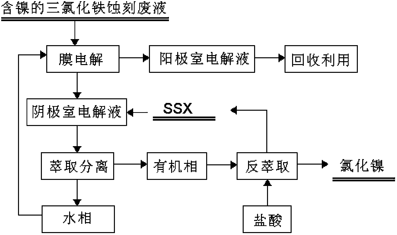
Recovery method for waste ferric trichloride etching liquid
A technology of ferric chloride and recovery method, applied in chemical instruments and methods, metallurgical wastewater treatment, water/sludge/sewage treatment, etc., to achieve the effects of less operating costs, no three waste discharges, good environmental benefits and economic benefits
- Summary
- Abstract
- Description
- Claims
- Application Information
AI Technical Summary
Problems solved by technology
Method used
Image

Examples
Embodiment 1
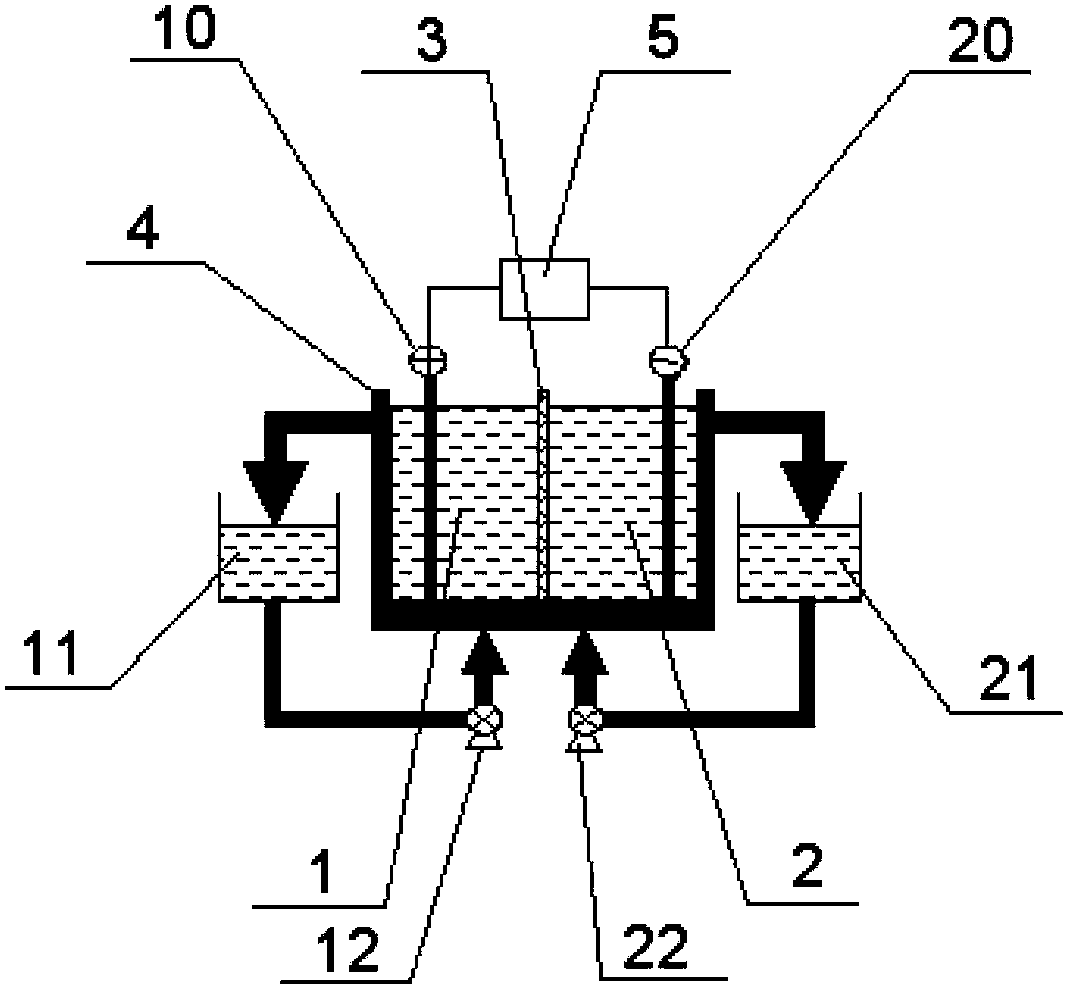
[0123] 1L of waste etching solution 1 was added to the anode chamber and cathode chamber liquid storage tank of the electrolytic cell composed of heterogeneous positive membranes, and the membrane polarization curve was measured at room temperature. It can be seen that the voltage increases linearly with the current. In order to better understand the influence of the electrolysis voltage on the electrolysis effect, the electrolysis test was carried out at the electrolysis cell voltage of 2.5, 3.0, 3.5, and 4.0V. Analyze the ferrous ions and iron ions in the sample. The total electrolysis time is 3.0h. After 3 hours of electrolysis, analyze the concentration of free acid and chloride ion. 2+ The amount of material change is used to calculate the current efficiency. The experimental results are shown in Table 1-1, Table 1-2, and Table 1-3.
[0124] Table 1-1, Fe in cathode and anode storage tanks during electrolysis 2+ Concentration change table
[0125]
[0126] Table 1-2...
Embodiment 2
[0132] Add 1 L of waste etching solution 1 into the anode chamber and the cathode chamber. Different ion-exchange membranes were selected, electrolyzed at a constant voltage of 3.0V, and the total electrolysis time was 3.0h. In the experiment, 25 mL samples were taken in the anode storage tank and cathode storage tank every half hour, and the ferrous ions, iron ions, and free acid and chloride ion concentrations after electrolysis for 3 hours were analyzed, and the electrolysis current efficiency was calculated. As in Table 2-1 and 2-2. It can be seen from Table 2-1 and 2-2 that Fe ions migrate through the cathodic membrane to the cathode chamber in the electrolytic cell composed of heterogeneous cathodic membrane, and the electrolysis effect is better for heterogeneous cathodic membrane electrolyzer than homogeneous cathodic membrane electrolyzer. The heterogeneous negative film electrolyzer is the worst. From the perspective of free acid concentration (Table 2-3), using th...
Embodiment 3
[0140] There is no Na in the waste etching solution 2 + and H in acid + As a conductive ion, the negative membrane is selected to form an electrolytic cell for steady flow test. Add 3L of waste etching solution 2 to the anode storage tank, add 600ml of waste etching solution 2 to the cathode storage tank, and in a steady flow state, first perform electrolysis at a low current of 3.60A for 2 hours and then at a high current of 5.6A for 3 hours , the ferrous ions reacted to the anode are all oxidized to ferric ions. During this period, sample 25ml and 10ml in the anode chamber and the cathode chamber respectively every 1h or 2h (select specific questions), and analyze the ferrous ions and iron ions in the samples, as well as the free acid in the solution in each storage tank after electrolysis and chloride ion concentration and calculate the current efficiency. The results are shown in Table 3-1.
[0141] Table 3-1, 5.60A steady current electrolysis test results table
[01...
PUM
| Property | Measurement | Unit |
|---|---|---|
| current efficiency | aaaaa | aaaaa |
Abstract
Description
Claims
Application Information