High-energy density lithium ion battery formation method
A lithium-ion battery and high energy density technology, applied in the field of lithium batteries, can solve the problems of unsuitable lithium-rich-carbon anode with extremely high energy density batteries, poor rate performance, and high charging voltage, so as to reduce the initial capacity loss and flatulence , to avoid the effect of deterioration
- Summary
- Abstract
- Description
- Claims
- Application Information
AI Technical Summary
Problems solved by technology
Method used
Image
Examples
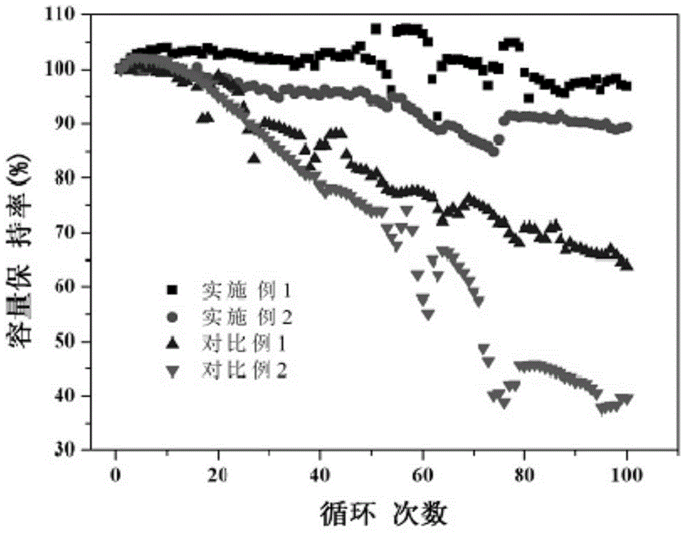
Embodiment 1
[0030] First make the battery:
[0031] Weigh the material according to the mass ratio of lithium-rich cathode material: PVDF (polyvinylidene fluoride): Super P (conductive carbon black): KS-6 (flake graphite conductive agent) = 94: 2.5: 3: 0.5, and dry Remove moisture. Dissolve PVDF into NMP (N-methylpyrrolidone) to make PVDF glue, add Super P and KS-6 to it and stir to make conductive agent glue, then add lithium-rich positive electrode material to it, stir evenly, and then According to 110g / m 2 The density on one side of the aluminum foil is uniformly coated on both sides of the aluminum foil, dried at 100°C for 10 hours, then rolled, cut into positive electrode sheets, and positive electrode tabs are spot welded.
[0032] Weigh the material according to the mass ratio of graphite: Super P (conductive carbon black): SBR (styrene-butadiene rubber): CMC (sodium carboxymethyl cellulose) = 93.2: 2.5: 2.5: 1.8, wherein SBR is in the state of emulsion, and other materials Bake...
Embodiment 2
[0049]Weigh the material according to the mass ratio of lithium-rich cathode material: PVDF (polyvinylidene fluoride): Super P (conductive carbon black): KS-6 (flake graphite conductive agent) = 94: 2.5: 3: 0.5, and dry Remove moisture. Dissolve PVDF into NMP (N-methylpyrrolidone) to make PVDF glue, add Super P and KS-6 to it and stir to make conductive agent glue, then add lithium-rich positive electrode material to it, stir evenly, and then According to 120g / m 2 The density on one side of the aluminum foil is uniformly coated on both sides of the aluminum foil, dried at 100°C for 10 hours, then rolled, cut into positive electrode sheets, and positive electrode tabs are spot welded.
[0050] Weigh the material according to the mass ratio of silicon carbon negative electrode material: PVDF (polyvinylidene fluoride): Super P (conductive carbon black) = 94.5: 5: 0.5, and dry to remove water. Dissolve PVDF into NMP (N-methylpyrrolidone) to make PVDF glue, add Super P to it and ...
Embodiment 3
[0088] The manufacturing process of the positive and negative electrodes is exactly the same as that of Example 1, except that the active material of the negative electrode is changed to MCMB (mesophase carbon microspheres). Wind the positive electrode sheet, diaphragm, and negative electrode sheet into a square core, put them into a square aluminum shell, bake at 85°C for 24 hours, and inject a 4.5V high-voltage resistant electrolyte.
[0089] Formation of battery:
[0090] (1) After the battery injection is completed, add sealing cotton to the liquid injection hole, and fix the sealing cotton with transparent tape, and let it stand for 30 hours;
[0091] (2) Charge to 4.0V at a rate of 0.01C,
[0092] (3) Charge to 4.2V at a rate of 0.03C;
[0093] (4) Charge to 4.4V at a rate of 0.1C;
[0094] (5) 4.4V constant voltage charging for 2h;
[0095] (6) Aging the battery at 80°C for 1 hour. After aging, place the battery in a vacuum box to evacuate the air, then weigh the ba...
PUM
 Abstract
Description
Claims
Application Information
 - R&D
- Intellectual Property
- Life Sciences
- Materials
- Tech Scout
- Unparalleled Data Quality
- Higher Quality Content
- 60% Fewer Hallucinations
Browse by: Latest US Patents, China's latest patents, Technical Efficacy Thesaurus, Application Domain, Technology Topic, Popular Technical Reports.
© 2025 PatSnap. All rights reserved.Legal|Privacy policy|Modern Slavery Act Transparency Statement|Sitemap|About US| Contact US: help@patsnap.com

