
Focused ion beam sample preparation method for precisely positioning front-layer defects

A technology of focusing ion beams and precise positioning, which is applied in the preparation of test samples, material analysis by measuring secondary emissions, etc. It can solve the problems of optical lens observation quality, optical lens pollution, and impact on positioning, etc., to save defects The effect of positioning time, improving yield, and avoiding product loss

Active Publication Date: 2014-12-10
SHANGHAI HUALI MICROELECTRONICS CORP
View PDF7 Cites 5 Cited by
  • Summary
  • Abstract
  • Description
  • Claims
  • Application Information

AI Technical Summary

Problems solved by technology

The disadvantage of this method is that because FIB is a destructive inspection, a large number of particles caused by cutting will be suspended in the entire cavity, and these suspended particles will cause huge pollution to the optical lens, and also have a huge impact on the observation quality of the optical lens. It will not be clear whether it is a defect in the front layer of the sample or a defect in the cavity, which will affect the final positioning

Method used


Image

  • Focused ion beam sample preparation method for precisely positioning front-layer defects
  • Focused ion beam sample preparation method for precisely positioning front-layer defects
  • Focused ion beam sample preparation method for precisely positioning front-layer defects

Examples


Embodiment Construction

[0020] In order to make the content of the present invention clearer and easier to understand, the content of the present invention will be described in detail below in conjunction with specific embodiments and accompanying drawings.

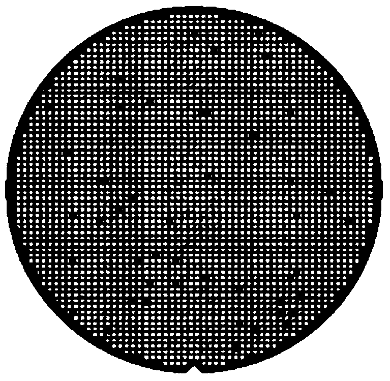
[0021] On-line defect inspection is performed on the wafer to find out the defects; in the case of finding out the defects, use a scanning electron microscope (SEM) or an optical microscope (OM, optical microscope) to observe the specific shape of the defect and infer the cause of the defect.

[0022] If the scanning electron microscope SEM cannot observe the defect or determine the cause of the defect, and the observation results of the optical microscope OM cannot determine the cause of the defect, then use the focused ion beam machine FIB failure analysis method to conduct a cross-sectional analysis of the defect, and according to the results Determine the cause of the defect.

[0023] If the scanning electron microscope SEM can observe the d...


PUM


Abstract

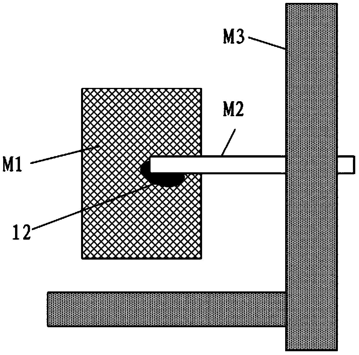
The invention provides a focused ion beam sample preparation method for precisely positioning front-layer defects. The method comprises the following steps: carrying out online defect detection on a wafer to find out the defects and observing the specific features of the defects by using a scanning electron microscope or an optical microscope; if the scanning electron microscope cannot observe the defects or judge the reasons of the defects and the reasons of the defects cannot be judged according to the observation result of the optical microscope, firstly obtaining the microscopic observation result by using the optical microscope and then carrying our defect positioning by means of the microscopic observation result and the information of different layers of photo masks, obtained a wafer product design process.

Description

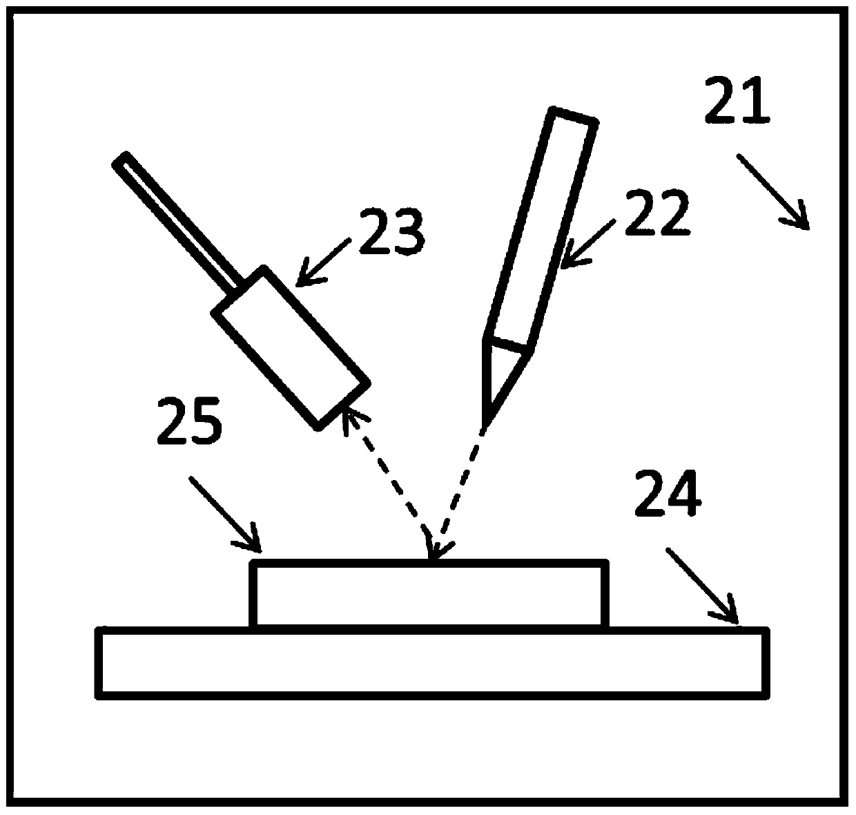
technical field [0001] The invention relates to the field of focused ion beam machines, and more specifically, the invention relates to a focused ion beam sample preparation method for precisely locating defects in the front layer. Background technique [0002] The Focused Ion Beam (FIB) system is a microdissection instrument that uses an electric lens to focus the ion beam into a very small size. The existing focused ion beam machines use ions as the electron microscope inspection function, such as figure 1 As shown, it includes a cavity 21, an ion source 22, an electron detector 23, and a sample seat 24. The ion source 22 emits an ion beam that bombards the surface of a sample 25 on the sample seat to generate electrons, and the bombarded secondary electrons and backscattered electrons Then the electronic detector 23 collects the signal for imaging, which is the so-called electron microscopic image. [0003] However, the current FIB machine uses ions as the electron micro...

Claims


Application Information

Patent Timeline
IPC IPC(8): G01N1/28G01N23/22
Inventor 范荣伟陈宏璘龙吟顾晓芳刘祚钺
Owner SHANGHAI HUALI MICROELECTRONICS CORP
Learn More