A high-speed railway catenary system lightning waveform online monitoring device

A high-speed railway and monitoring device technology, which is applied in the direction of circuit devices, battery circuit devices, collectors, etc., can solve problems such as unsatisfactory sampling frequency and clock accuracy of devices or systems, great influence of solar cells, and equipment failure. Achieve the effect of optimizing space layout, simple structure design, and ensuring power supply

Active Publication Date: 2017-04-12
WUHAN UNIV +2
View PDF5 Cites 2 Cited by
  • Summary
  • Abstract
  • Description
  • Claims
  • Application Information

AI Technical Summary

Problems solved by technology

Invention patent CN 101937015 A discloses an online monitoring device for lightning current and lightning voltage waveform parameters of overhead transmission lines, which includes: voltage sensors, current sensors, power coils, voltage conditioning and energy storage modules, etc. The mouth type Rogowski coil current sensor and the capacitive coupling voltage sensor collect the lightning current and lightning voltage signals on the wire respectively (however, the device does not have a clock unit to provide time records for the occurrence of lightning current)
Invention patent CN 101923109 A discloses a lightning strike waveform monitoring system for transmission line conductors. The system includes a host, a server that can be connected to the host through a GPRS network, and a plurality of extensions on the line that are connected to the host by wireless communication. The feature is that the extension mainly Collect and adjust the lightning current signal, the host mainly processes and stores the information received from the extension, and the server mainly performs system setting, basic data management, data statistical analysis, etc. It is supplied by induction and has no battery, so the system will not work properly in the event of a power outage or a lightning strike)
Invention patent CN 103592506 A discloses an online lightning current monitoring device for overhead transmission lines, which is composed of MSP430 single-chip microcomputer, FPGA field programmable gate array, trigger circuit, AD acquisition and matching circuit, etc. It is characterized in that the device is powered by solar cells and includes A number of sensors erected on the insulators of the transmission tower and the lightning protection wire of the tower adopt the mode of waking up to work and sleeping when not working, which has achieved the purpose of reducing power consumption (however, the power supply method of its solar battery plus battery has the following problems: 1. The weather has a great impact on the solar battery, continuous rainy days may cause the battery to be insufficient, and the device cannot work normally)
Invention patent CN 103412185 A discloses a lightning current detection device, including a signal conditioning unit, an energy harvesting unit, and an acquisition unit. When it happens, it can work at the same time, monitor the information of the lightning strike in real time, and does not need an external trigger circuit (however, the device only records the moment, amplitude and polarity of the lightning strike, and does not record other parameters of the lightning current)
[0008] Generally speaking, at present, there are many measurements and researches on lightning current parameters of ordinary high-voltage transmission lines. Some studies lack experimental basis and have defects. In view of the characteristics of high frequency and short duration of lightning current, the sampling frequency of related devices or systems should be timely. Clock accuracy is not ideal

Method used


Image

  • A high-speed railway catenary system lightning waveform online monitoring device
  • A high-speed railway catenary system lightning waveform online monitoring device
  • A high-speed railway catenary system lightning waveform online monitoring device

Examples


Embodiment

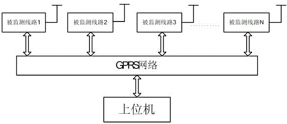
[0027] like figure 1 As shown, it is the lightning waveform online monitoring network of the high-speed railway catenary system. The network should be equipped with a fixed IP host computer. The network can cover all areas with GPRS signals. Networks are deployed on several lines in the area, and each line Several devices for monitoring lightning waveforms according to the present invention are installed on the monitored catenary lines, and the designated devices are uniquely identified by the area ID and equipment ID solidified in the device.

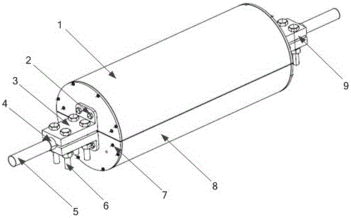
[0028] In the present invention, the appearance diagram of the lightning waveform online monitoring device is as follows figure 2 As shown, the chassis shell of the online monitoring device is in the shape of a cylinder, and is divided into two upper and lower boxes. The upper shell 1 and the lower shell 8 of the box are made of aluminum alloy, which not only reduces the weight of the entire device, but also It can also prevent the i...


PUM


Abstract

The invention discloses a thunder and lightning waveform on-line monitoring device of an high-speed railway overhead line system. The thunder and lightning waveform on-line monitoring device of the high-speed railway overhead line system comprises a power supply module, a remote control switch, an i-Core 2 core board, a colleting circuit, a thunder and lightning flow sensor, a time service module, a GPRS network module, a machine case shell, a limiting cushion block and the like. The thunder and lightning waveform on-line monitoring device is erected on a backflow wire of a monitored overhead line, when the overhead line system is struck by thunder, the thunder and lightning flow sensor obtains sensing voltage, the collecting circuit collects thunder and lightning flow waveform signals, collected information is sent to an upper computer through a wireless network, a lithium battery is charged through an electricity taking coil coupling electricity taking method, and an external power source is not needed. The thunder and lightning waveform on-line monitoring device of the high-speed railway overhead line system provides an original basis for mastering thunder and lightning waveforms, resisting thunder scientifically, analyzing thunder strike accidents and positioning thunder strike faults, and is simple in structure, convenient to install and maintain and reliable in work.

Description

technical field [0001] The invention belongs to the field of lightning information measurement and lightning protection (fault location, lightning waveform acquisition) of a high-speed railway catenary system, and relates to an online monitoring device for lightning waveforms of a high-speed railway catenary system. Background technique [0002] Catenary is one of the core technologies of high-speed railways. As an important part of the traction power supply system of electrified railways, it is responsible for the important task of continuously transmitting electric energy to electric locomotives running along the line. The number and speed of emergency repairs will directly affect the performance of electrified railway transportation capacity and its safety and stability. [0003] The distribution of high-speed railways in my country is becoming more and more extensive, and the meteorological conditions in the passing areas are quite different, and the characteristics of t...

Claims


Application Information

Patent Timeline
Patent Type & Authority Patents(China)
IPC IPC(8): G01R19/25H02J7/02H02J7/00
Inventor 肖晓晖杨帆方志国戚广枫李红梅游鹏辉
Owner WUHAN UNIV
Why Eureka
Try Eureka