A method for separating and purifying methane containing hydrogen and carbon monoxide to produce liquefied natural gas

A technology for liquefied natural gas and carbon monoxide, which is used in the separation of methane-rich gas and the chemical industry to achieve the effects of large processing capacity, high operating flexibility and convenient circulation

Active Publication Date: 2017-02-15
CHENGDU SEPMEM SCI & TECH
View PDF5 Cites 0 Cited by
  • Summary
  • Abstract
  • Description
  • Claims
  • Application Information

AI Technical Summary

Problems solved by technology

[0006] The purpose of the present invention is to provide a hydrogen-containing, carbon monoxide-containing gas for the current urgent need for a kind of methane-rich gas such as coke oven gas, methanol purge gas, and coal gas to be separated so as to utilize the effective components. Method for producing liquefied natural gas by separating and purifying methane gas

Method used


Image

  • A method for separating and purifying methane containing hydrogen and carbon monoxide to produce liquefied natural gas
  • A method for separating and purifying methane containing hydrogen and carbon monoxide to produce liquefied natural gas

Examples


Embodiment 1

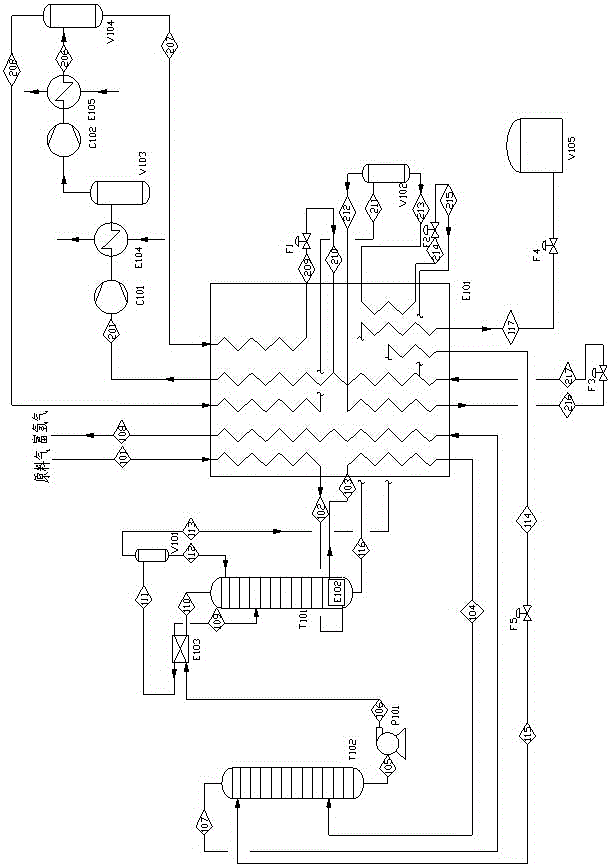
[0054] The flow chart of this embodiment is as figure 1 As shown, the nitrogen-containing methane gas listed in this embodiment is purified coke oven gas. The process steps of using the gas to produce liquefied natural gas (LNG) and hydrogen-rich gas through double-tower rectification are as follows.

[0055] (1) Raw material gas pre-cooling

[0056] The raw material gas 101 enters the liquefaction device, and the raw material gas 101 is first condensed in the condensing evaporator E101 to a liquid state or partially condensed to a liquid state to obtain the primary cooling raw material 102. The primary cooling raw material 102 is sent to the kettle reboiler E102 of the high-pressure tower T101 to provide heat, while the primary cooling raw material 102 is cooled, and the cooled primary cooling raw material 103 enters the condensing evaporator E101 of the liquefaction unit for deep cooling. It is cooled to a full liquid state, and a cryogenic raw material gas 104 is obtained.

[00...

Embodiment 2

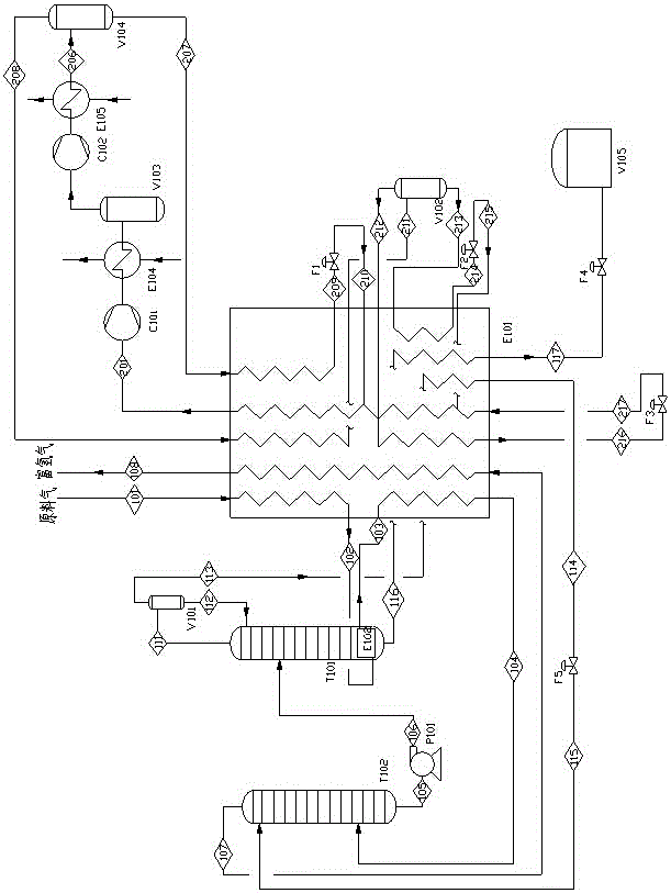
[0076] The flow chart of this embodiment is as figure 2 As shown, the nitrogen-containing methane gas enumerated in this embodiment is purified coke oven gas, and the process steps of using this gas to produce liquefied natural gas (LNG) and hydrogen-rich gas through double-tower rectification are as follows.

[0077] (1) Raw material gas pre-cooling

[0078] The raw material gas 101 is first condensed to nearly liquid or partially condensed to liquid in the condensing evaporator E101 to obtain the primary cooling raw material 102. The primary cooling raw material 102 is sent to the kettle reboiler E102 of the high-pressure tower T101 to provide heat, while the primary cooling raw material 102 is cooled, and the cooled primary cooling raw material 103 enters the condensing evaporator E101 of the liquefaction unit for deep cooling. It is cooled to a full liquid state, and a cryogenic raw material gas 104 is obtained.

[0079] (2) Low pressure column T102 distillation

[0080] The cry...


PUM


Abstract

The invention discloses a method for separating and purifying methane gas containing hydrogen and carbon monoxide to produce liquefied natural gas. To use the problem of active ingredients. It includes the following steps: raw material gas cooling, rectification in low-pressure tower, separation and reflux of stream at the top of high-pressure tower, rectification in high-pressure tower, and refrigeration. The present invention adopts the cryogenic double-tower rectification process, through which the easily volatile components and the less volatile components in coke oven gas and coal gas can be separated, and the purity of the obtained product hydrogen and carbon monoxide can reach more than 95%. As raw material gas for other chemical industries, liquefied natural gas can also be obtained at the same time. The invention has reasonable design, can effectively reduce energy consumption, and at the same time, the prepared product has the characteristics of high purity, can also directly obtain liquefied natural gas, and realizes the comprehensive utilization of methane gas containing hydrogen and carbon monoxide such as coke oven gas.

Description

Technical field [0001] The invention relates to the field of chemical engineering, especially the field of methane-rich gas separation, and specifically relates to a method for separating and purifying methane gas containing hydrogen and carbon monoxide to prepare liquefied natural gas. The invention can separate and purify methane-rich gas such as coke oven gas, methanol purge gas, coal gas production, etc., and prepare hydrogen-rich and carbon monoxide gas and liquefied natural gas. Background technique [0002] Coke oven gas, also known as crude gas or raw gas, refers to the use of several bituminous coals to make coking coal. After high-temperature dry distillation in the coke oven, it produces coke and tar products while producing a kind of combustibility. gas. As a by-product of the coking industry, it contains many combustible components and belongs to high-calorific value gas. As a mixture of coke oven gas, its yield and composition vary depending on the quality of the ...

Claims


Application Information

Patent Timeline
Patent Type & Authority Patents(China)
IPC IPC(8): C10L3/08
CPCF25J3/0223F25J3/0233F25J3/0271F25J2200/74F25J2200/78F25J2210/14F25J2215/04F25J2270/18F25J2270/66F25J2290/34
Inventor 张惊涛
Owner CHENGDU SEPMEM SCI & TECH
Why Eureka
Try Eureka