
Resistive gate tunneling field effect transistor and preparation method thereof

A tunneling field effect and transistor technology, which is applied in semiconductor/solid-state device manufacturing, semiconductor devices, electrical components, etc., can solve the problems of switching speed, operating times and integration that cannot be ignored, and achieve fast speed, optimize sub-threshold characteristics, The effect of low operating voltage

Inactive Publication Date: 2015-02-04
PEKING UNIV
View PDF8 Cites 17 Cited by
  • Summary
  • Abstract
  • Description
  • Claims
  • Application Information

AI Technical Summary

Problems solved by technology

However, the device's switching speed, operating times and integration issues cannot be ignored.

Method used


Image

  • Resistive gate tunneling field effect transistor and preparation method thereof
  • Resistive gate tunneling field effect transistor and preparation method thereof
  • Resistive gate tunneling field effect transistor and preparation method thereof

Examples


Embodiment Construction

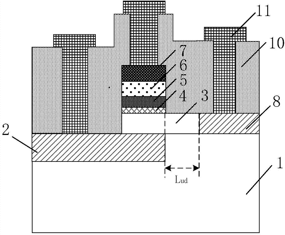
[0043] The present invention will be further described below by example. It should be noted that the purpose of the disclosed embodiments is to help further understand the present invention, but those skilled in the art can understand that various replacements and modifications are possible without departing from the spirit and scope of the present invention and the appended claims of. Therefore, the present invention should not be limited to the content disclosed in the embodiments, and the protection scope of the present invention is subject to the scope defined in the claims.

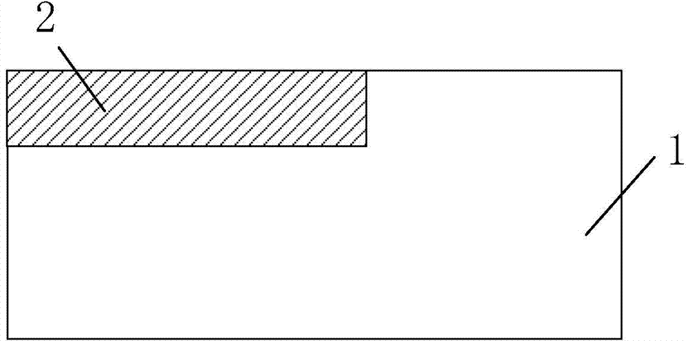
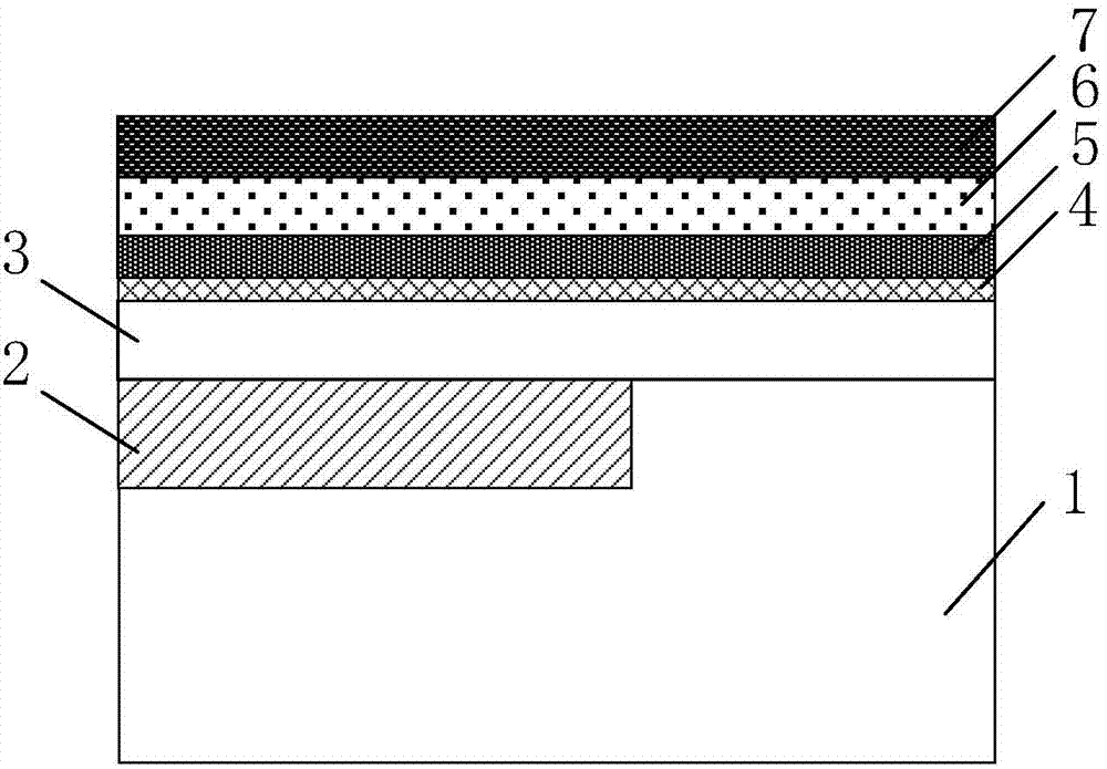
[0044] A specific example of the preparation method of the present invention includes Figure 2 to Figure 6 Process steps shown:

[0045] 1. On the silicon substrate 1 of a high-resistance bulk silicon wafer with a crystal orientation of (100), the shallow trench isolation technology is used to fabricate an active region isolation layer; then photolithography exposes the tunneling source region, us...


PUM

PropertyMeasurementUnit
Thicknessaaaaaaaaaa

Abstract

Disclosed is a resistive gate tunneling field effect transistor. The resistive gate tunneling field effect transistor comprises a control gate layer, a gate medium layer, a semiconductor substrate, a tunneling source area, a low-doped leakage area and a channel region. A control gate employs a gate stack structure and is successively composed of a bottom electrode layer, a volatile resistive material layer and a top electrode layer. The volatile resistive material layer is a material layer with a volatile resistive characteristic. The channel region is disposed above the tunneling source area and is partially overlapped with the tunneling source area in terms of position, a tunneling junction is formed at the interface of the channel region and the tunneling source area; the low-doped leakage area is disposed at the other side of the horizontal direction of the control gate and is spaced from the control gate by a horizontal interval; the low-doped leakage area and the tunneling source area are doped with impurities of different doping types; and the doping types of the semiconductor substrate and the channel region are consistent with that of the tunneling source area. The structure has large on-state currents and a steep subthreshold slope, and can satisfy the application demand of a low-voltage low-power logic device and a logic circuit when working under the condition of low bias.

Description

technical field [0001] The invention belongs to the field of field effect transistor logic devices and circuits in CMOS ultra large integrated circuits (ULSI), and in particular relates to a resistive gate tunneling field effect transistor and a preparation method thereof. Background technique [0002] As the size of metal-oxide-silicon field-effect transistors (MOSFETs) continues to shrink, especially when the feature size of the device enters the nanometer scale, the negative effects of the short channel effect of the device become more and more obvious. Drain-induced barrier-lowering effect (DIBL) and band-band tunneling effect increase the off-state leakage current of the device, which increases the power consumption of the integrated circuit along with the decrease of the threshold voltage of the device. And the subthreshold current conduction of traditional MOSFET devices is limited by the diffusion mechanism, and the limit value of the subthreshold slope at room tempe...

Claims


Application Information

Patent Timeline
IPC IPC(8): H01L29/78H01L29/49H01L21/336
CPCH01L29/7835H01L29/401H01L29/495H01L29/4958H01L29/66446H01L29/66492H01L29/66969
Inventor 黄如黄芊芊吴春蕾王佳鑫朱昊王阳元
Owner PEKING UNIV
Learn More