Adaptive line loss compensation circuit for DC-DC (direct current) converter

A DC-DC, line loss compensation technology, applied in the direction of converting DC power input to DC power output, instruments, electrical components, etc., can solve the problems of difficult to achieve, limited process, and high performance requirements, to reduce process costs and simplify compensation. The effect of simple circuit and circuit structure

Inactive Publication Date: 2015-02-04
SUN YAT SEN UNIV
View PDF1 Cites 17 Cited by
  • Summary
  • Abstract
  • Description
  • Claims
  • Application Information

AI Technical Summary

Problems solved by technology

Therefore, for a DC-DC converter that already contains an external current limiting resistor, adding a high-side current sense resistor will significantly reduce its conversion efficiency
[0007] Second, the chip uses a transistor current mirror, and with the deviation of the process, there will be a certain error when the current mirror mirrors the current
[0008] Third, the chip needs to use a high-precision and small offset (offset) op amp, which requires high performance and is difficult to achieve.
[0009] Fourth, the chip needs to use BJT transistors, which limits the technology used, and cannot use the full CMOS process, which increases the process cost of the chip

Method used


Image

  • Adaptive line loss compensation circuit for DC-DC (direct current) converter
  • Adaptive line loss compensation circuit for DC-DC (direct current) converter
  • Adaptive line loss compensation circuit for DC-DC (direct current) converter

Examples


Embodiment 1

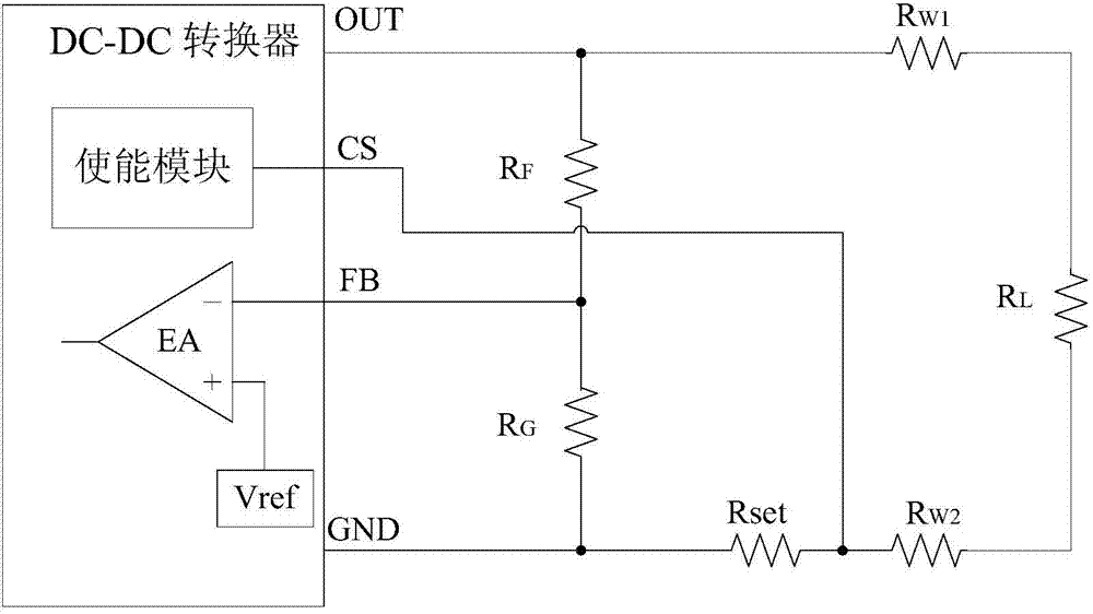
[0035] The circuit structure of the DC-DC converter adopted in the present invention is as image 3 shown with an external current limiting resistor. Among them, R W1 , R W2 Is the resistance of the power line, Rset is an external current limiting resistor, it can detect the load current, and output a CS terminal voltage signal proportional to the load current. When the load current exceeds the preset threshold, the CS signal will turn off the DC-DC converter to protect the DC-DC converter. When the DC-DC converter works normally, the signal voltage at the FB terminal is equal to the reference voltage Vref. When using this converter, the output voltage OUT can be set by adjusting the ratio of the voltage dividing resistors RF and RG.

Embodiment 2

[0037] Such as Figure 4 As shown, the line loss compensation circuit of the present invention includes an operational amplifier A, an NMOS transistor M, a low-side current sampling resistor Rset and a compensation resistor Rcom. One end of the low-side current sampling resistor Rset and the compensation resistor Rcom are commonly grounded, the other end of Rset is connected to the CS terminal, and the other end of Rcom is connected to the Vcom terminal; the non-inverting input terminal of the operational amplifier A is connected to the CS terminal, and the inverting input terminal of the operational amplifier A The terminal is connected to the Vcom terminal, and the output terminal of the operational amplifier A is also connected to the gate of the NMOS transistor M; the source of the NMOS transistor M is connected to the Vcom terminal, and the drain of the NMOS transistor M is connected to the FB terminal.

[0038] When the DC-DC converter works normally, the signal voltage ...

Embodiment 3

[0043] The circuit of the present invention is applied to a current mode, PWM control, step-down DC-DC converter. The input voltage of the converter is 12V, the output voltage is set to 5V, Rset=100mΩ, R W1 =R W2 =50mΩ, when the load current jumps from 0.5A to 3A, the voltage at both ends of the load before and after line loss compensation is as follows: Figure 5 shown.

[0044] Load regulation is defined as the change of output voltage caused by the change of unit load current, and its mathematical expression is based on Figure 5 Based on the simulation results, the load regulation rate before and after compensation can be calculated.

[0045] Before compensation: LR 0 = 4.93 V - 4.42 V 3.00 A - 0.50 A = 0.204 ...


PUM


Abstract

The invention discloses an adaptive line loss compensation circuit for a DC-DC (direct current) converter. The adaptive line loss compensation circuit comprises an operational amplifier, an NMOS (N-channel metal oxide semiconductor) tube, a low-side current sampling resistor and a compensation resistor, one end of the low-side current sampling resistor and one end of the compensation resistor are jointly grounded, the other end of the low-side current sampling resistor is connected with a CS end, the other end of the compensation resistor is connected with a Vcom end, an in-phase input end of the operational amplifier is connected with the CS end, an inverted input end of the operational amplifier is connected with the Vcom end, an output end of the operational amplifier is connected with a grid electrode of the NMOS tube, a source electrode of the NMOS tube is connected with the Vcom end, and a drain electrode of the NMOS tube is connected with an FB end of the DC-DC converter. The adaptive line loss compensation circuit has the advantages that the conversion efficiency of the DC-DC converter cannot be affected, the adaptive line loss compensation circuit is high in precision and easy to implement, and a full CMOS (complementary metal oxide semiconductor) process can be adopted. The adaptive line loss compensation circuit can be widely applied to the field of integrated circuits.

Description

technical field [0001] The invention relates to the technical field of integrated circuits, in particular to an adaptive line loss compensation circuit of a DC-DC converter. Background technique [0002] The DC-DC converter is a power supply that uses modern power electronics technology to maintain a stable output voltage by controlling the time ratio of the switching device on and off. With the development and application of large-scale and ultra-large-scale integrated circuits, the operating current range of DC-DC converters is increasing. When powering remote loads, DC-DC converters require very long power lines to connect. In the past, it was generally believed that the resistance of the power line was very small, so the influence of the resistance of the power line was directly ignored when considering the output voltage of the converter. However, as the supply current increases, the voltage loss on the power line can no longer be ignored. Such as figure 1 As shown,...

Claims


Application Information

Patent Timeline
Patent Type & Authority Applications(China)
IPC IPC(8): H02M3/155
Inventor 郭建平祝磊陈弟虎丁喜冬
Owner SUN YAT SEN UNIV
Why Eureka
Try Eureka