
Synchronous rectification device for water-cooled laminated busbars suitable for high current transmission

A technology of stacked busbars and synchronous rectification, applied in output power conversion devices, conversion of AC power input to DC power output, electrical components, etc. Current carrying capacity, conducive to self-cooling and heat dissipation, and the effect of increasing conductive cross-section

Active Publication Date: 2017-01-18
GUANGZHOU QINGTIAN INDAL
View PDF10 Cites 0 Cited by
  • Summary
  • Abstract
  • Description
  • Claims
  • Application Information

AI Technical Summary

Problems solved by technology

[0004] The laminated busbar is a multi-layer composite structure connection bar. The existing laminated busbars are all self-cooling. In the case of synchronous rectification with large currents, neither self-cooling nor air-cooling can meet the high requirements of large currents on heat dissipation efficiency. Therefore, adding water cooling on the basis of laminated busbars has become an urgent solution

Method used


Image

  • Synchronous rectification device for water-cooled laminated busbars suitable for high current transmission
  • Synchronous rectification device for water-cooled laminated busbars suitable for high current transmission
  • Synchronous rectification device for water-cooled laminated busbars suitable for high current transmission

Examples


Embodiment Construction

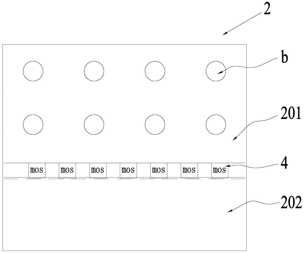
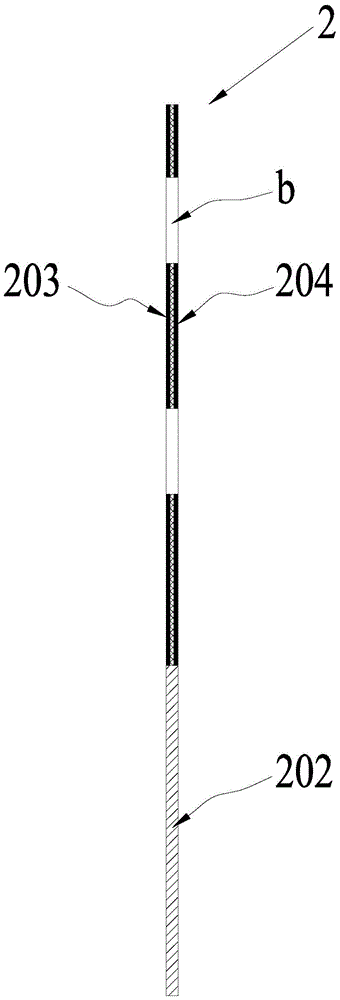
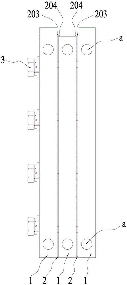
[0030] Such as Figure 1 to Figure 3 As shown, the water-cooled laminated busbar suitable for large current transmission according to the preferred embodiment of the present invention includes three conductive substrates 1 and two circuit boards 2 .

[0031] The circuit board 2 is a PCB board divided into a copper clad area 201 and a welding area 202. The front and back sides of the PCB are respectively provided with a front copper clad layer 203 and a reverse copper clad layer 204. The front copper clad layer 203 and the reverse copper clad layer 204 are insulated from each other and are all located in the copper clad area 201, and the PCB board is provided with seven groups of pad groups located in the welding area 202, the pad groups include the first polarity pad electrically connected to the front copper clad layer 203 and the The pads of the second polarity electrically connected to the copper clad layer 204 on the reverse side are evenly arranged along the boundary line...


PUM


Abstract

The invention discloses a water-cooling layer bus bar suitable for large-current transmission and a synchronous rectifying device. The bus bar comprises two conductive substrates and a PCB, wherein a front copper coating layer and a back copper coating layer are arranged on the front side and back side of the PCB respectively and are insulated from each other, both the front copper coating layer and the back copper coating layer are located in a copper coating area, the PCB is provided with a bonding pad set located in the welding area and comprises a first polarity bonding pad electrically connected with the front copper coating layer and a second polarity bonding pad electrically connected with the back copper coating layer, the two conductive substrates and the PCB are arranged in an alternately stacked mode, the two conductive substrates are in close contact with the front copper coating layer and the back copper coating layer of the PCB respectively to achieve electric connection, each conductive substrate is provided with a cooling liquid passing hole, and a water inlet and a water outlet of each cooling liquid passing hole are formed in the surface, not in contact with the PCB, of the corresponding conductive substrate. The bus bar has the advantages of being compact in structure, high in cooling efficiency, high in current carrying capacity, low in inductance, low in impedance, and high in reliability.

Description

technical field [0001] The invention relates to a water-cooled laminated bus bar suitable for large current transmission, and also relates to a synchronous rectification device using the bus bar. Background technique [0002] In the power electronics industry, low voltage and high current have become the mainstream trend. In the case of low voltage and high current output, a large voltage drop will directly lead to an increase in rectification loss and a decrease in power supply efficiency. Synchronous rectification uses a special power device MOS tube with extremely low on-state resistance to replace the rectifier diode, which greatly reduces the rectification loss at the output end of the switching power supply, thereby improving the efficiency of the power supply, reducing the heat generation of the power supply itself, and meeting the high efficiency requirements of low-voltage and high-current switching power supplies. and small size needs. [0003] Laminated busbars a...

Claims


Application Information

Patent Timeline
Patent Type & Authority Patents(China)
IPC IPC(8): H02M7/00H02M7/217H05K7/20
CPCH02M7/003H02M7/217
Inventor 张兴旺王晓玲刘柱龙赖前程
Owner GUANGZHOU QINGTIAN INDAL
Learn More