Technological method for drilling fluid solid control circulation system

A process method and technology of circulation system, which are applied in the field of drilling fluid solid control circulation system technology, can solve the problems of affecting the treatment effect, high cost of accessories, no concentration process, etc., and achieve the effect of good concentration effect, reducing volume and increasing concentration.

Active Publication Date: 2015-04-08
山东能源重装集团莱芜装备制造有限公司 +1
View PDF9 Cites 3 Cited by
  • Summary
  • Abstract
  • Description
  • Claims
  • Application Information

AI Technical Summary

Problems solved by technology

This traditional waste drilling fluid treatment method has the following disadvantages: ①After the natural settlement of the mud, the clarified mud water above is recycled as drilling fluid. Because of the high viscosity and specific gravity of the mud, the solid particles in it can only be slightly reduced. If you continue to use this kind of mud, some cuttings and gravel will inevitably enter the mud pump with the mud and be sent to the bottom of the well again, causing the mud pump to be easily damaged and the life of the drill bit will be greatly shortened. The debris and sand damage the wall-building performance of the mud, and even cause accidents such as well collapse and drill sticking; Rainstorms and other water sources gather at the well site, and waste drilling fluid may leak into adjacent farmland, water bodies, and surface soil, damaging the ecological environment near the well site; ③ Currently, in-situ burial has been banned in some areas, and it is required to clean up after completion of the well , the cleaning work is time-consuming and costly; ④ The method of digging holes on the spot itself is labor-intensive and inefficient
Main disadvantages: ①The storage tank occupies a large area; ②High transportation costs; ③High cost; ④Low efficiency; In terms of the problem, the cost of weight and barite in the drilling fluid accounts for about 75% of the total material cost of the drilling fluid, and the useful part of the mud fluid cannot be recycled, resulting in high drilling operating costs
The purification process of drilling fluid solid control equipment is roughly: wellhead (drilling fluid returned) → drilling fluid shale shaker → vacuum degasser → drilling fluid desander → desilter → drilling fluid centrifuge → purified drilling fluid returns Wellhead, the main shortcomings: ① It is difficult to select th

Method used


Image

  • Technological method for drilling fluid solid control circulation system
  • Technological method for drilling fluid solid control circulation system

Examples


Embodiment Construction

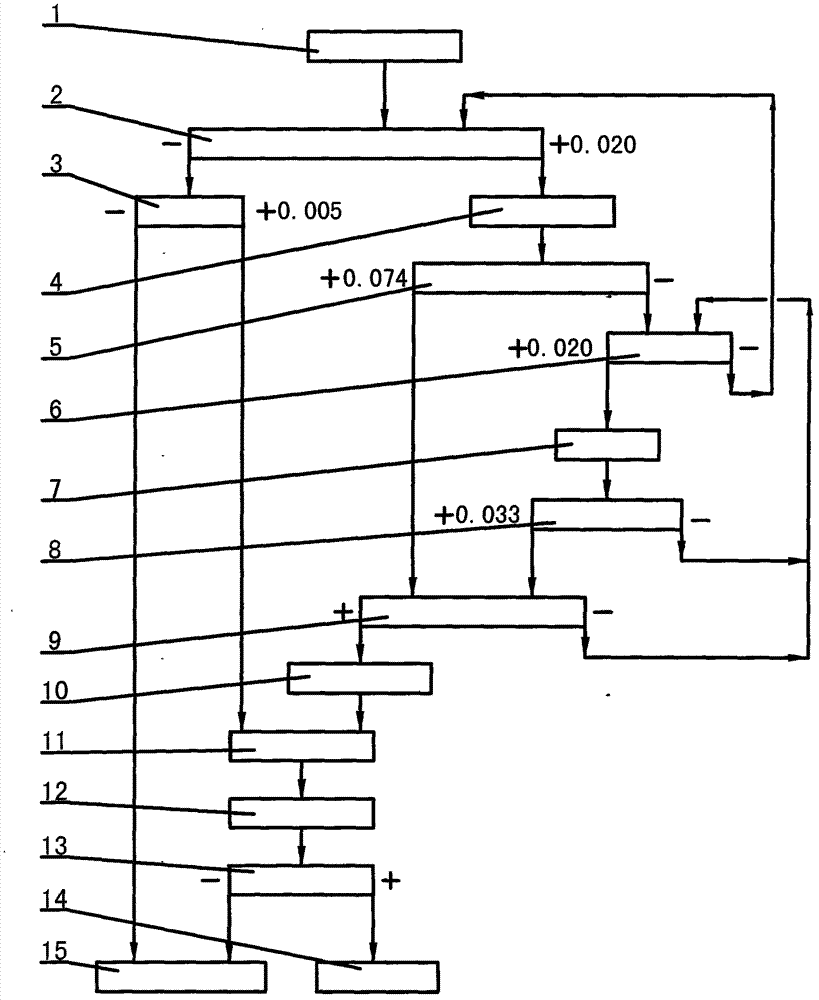
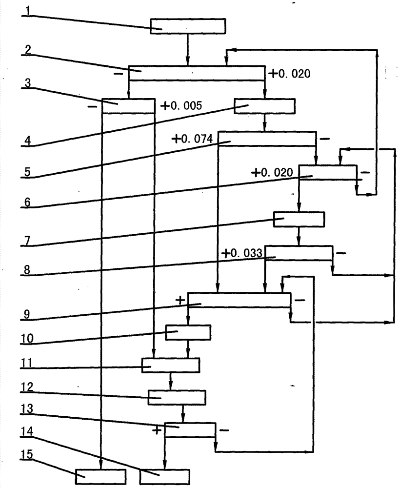
[0030] ① Drilling fluid (1) is concentrated and treated by the special concentration processor I (2), and classified into two parts: -0.020mm drilling fluid and +0.020mm drilling fluid: -0.020mm drilling fluid directly enters the special centrifuge (3 ) is classified into -0.005mm drilling fluid and +0.005mm drilling fluid after treatment, -0.005mm drilling fluid flows into the circulating fluid storage tank (15), and +0.005mm drilling fluid flows into the storage tank (11); The +0.020mm drilling fluid is transported to the special cyclone group I(5) through the oilfield mud pump I(4) and classified into two parts: -0.074mm drilling fluid and +0.074mm drilling fluid; ②Through the special cyclone group I (5) After classification, the +0.074mm drilling fluid flows directly into the special concentration processor III (9); the -0.074mm drilling fluid flows into the special concentration processor II (6), and the concentration is +0.020 after the concentration treatment mm drillin...


PUM


Abstract

The invention relates to a technological method for a drilling fluid solid control circulation system, in particular to a technological method for the treatment of drilling fluid produced during oil and gas drilling. The technological method for the drilling fluid solid control circulation system adopts the following device components: a special concentration treatment device I, a special centrifugal machine, an oil field mud pump I, a special cyclone set I, a special concentration treatment device II, an oil field mud pump II, a special cyclone set II, a special concentration treatment device III, an oil field mud pump III, a storage box, an oil field mud pump IV, a special filter press (or a special stacked spirals), a solid-phase mud cake collection barrel (or a mud transfer tank), and a circulating fluid storage tank. The technological method for the drilling fluid solid control circulation system has the following benefits: desanding, mud removal, destabilization and gel breaking in a circulating and classification manner are achieved through the two-stage special cyclone sets, so that the classifying effect is remarkable; circulating concentration is achieved through the three-stage special concentration treatment devices, so that the concentration effect is remarkable; the treated drilling fluid is recycled; treated solid-phase mud cakes or highly-concentrated mud are/is directly transported away.

Description

technical field [0001] The invention relates to a process method of a drilling fluid solid control circulation system, in particular to a process method for treating drilling fluid produced in the oil and gas drilling process. Background technique [0002] Drilling fluid is a circulating fluid used in the drilling process, which is a mixture of liquid, solid and chemical treatment agents. The circulation of drilling fluid is that after the drilling fluid is pressurized by the drilling pump to obtain water pressure, it is transported to the inner cavity of the drill pipe through the high-pressure manifold and the faucet, flows along the inner cavity of the drill pipe to the ground, and is sprayed out from the nozzle of the drill bit to put the drill bit in the formation. The broken cuttings are brought back to the ground along the annular space outside the drill pipe, and the large cuttings, barite and other large solid particles in the (mud) returned to the ground from the w...

Claims


Application Information

Patent Timeline
IPC IPC(8): E21B21/06
CPCE21B21/01
Inventor 梁吉军史晓晖马达昌刘云明陈超蔺磊王聪亓洁舲任加新亓玉刘兴旺孙昌伟辛伟
Owner 山东能源重装集团莱芜装备制造有限公司
Why Eureka
Try Eureka