Device used for whole row scanning type laser projection display and synchronization control method thereof

A laser display and scanning device technology, applied in projection devices, optics, optical components, etc., can solve problems such as fire hazards, high laser beam power, and complex two-dimensional scanning devices

Active Publication Date: 2015-04-08
北京中光超影科技有限公司
View PDF6 Cites 17 Cited by
  • Summary
  • Abstract
  • Description
  • Claims
  • Application Information

AI Technical Summary

Problems solved by technology

Lamp projectors have less than 30% color gamut coverage
Laser point-by-point scanning projection imaging technology can have very high resolution, but the power of the laser beam is

Method used


Image

  • Device used for whole row scanning type laser projection display and synchronization control method thereof
  • Device used for whole row scanning type laser projection display and synchronization control method thereof
  • Device used for whole row scanning type laser projection display and synchronization control method thereof

Examples


no. 1 example

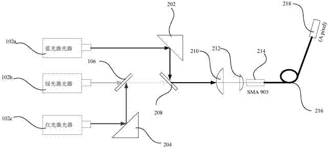
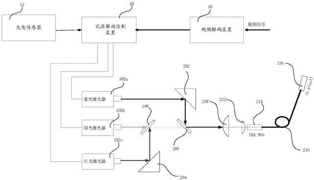
[0063] Please refer to figure 1 , which is a schematic diagram of an optical path formed by one pixel of the full-line scanning laser display device of the present application. Such as figure 1 As shown, the laser generator module 100 includes a red laser 102c, a green laser 102b and a blue laser 102a, a first dichroic mirror 106 and a second dichroic mirror 208, a first right-angle corner 204 and a second right-angle corner 202. The arrangement of the above optical devices is as follows figure 1 shown.

[0064] The red laser beam emitted by the red laser 102c is reflected by the first right-angle prism 204, and the direction of propagation is turned by 90° to irradiate on the first dichroic mirror 106; the first dichroic mirror 106 transmits green light and reflects red light; carefully Adjusting the distance between the first right-angled corner 204 and the red laser (that is, moving the first right-angled corner 204 in the horizontal direction), and rotating the firs...

no. 2 example

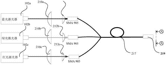
[0076] In this embodiment, the scanning device is the same as the above embodiment, except that the way of forming a single pixel is different. Please refer to Figure 6 , which is a schematic diagram of the optical path for forming a single pixel in the second embodiment of the scanning laser display device of the present application. In this embodiment, the laser generator module includes red, green, and blue three-color lasers (102c, 102b, 102a), and collimation elements (210a, 210b, 210c; 212a , 212b, 212c);

[0077] The light guide device includes an optical fiber corresponding to each laser, and the coupling end of each optical fiber is provided with a coupling joint SMA905 or an FC joint as the laser coupling interface; the coupling joint is arranged on the light guide In the collimated optical path of the laser corresponding to the fiber, and facing the incoming light direction, it is used to receive the laser beam emitted by the corresponding laser; bonded together...

no. 3 example

[0081] In this embodiment, the implementation of the monochrome pixel is basically the same as that of the above-mentioned second embodiment, the difference is that the light-emitting end surface of the optical fiber corresponding to one of the blue lasers 103b is provided with a phosphor coating, such as Figure 10 The phosphor coating shown in , was used to generate green light under blue laser excitation. Other aspects of this embodiment are the same as the above-mentioned second embodiment. The advantage of this embodiment is that the image speckle is very weak.

[0082] As mentioned above, a plurality of (such as 768) colored light beams are emitted by a one-dimensional imaging device or device, and after passing through a collimating lens and a cylindrical lens, they are irradiated to a rotating polygonal mirror (a regular octagonal prism in the above-mentioned embodiments of the application, in In actual use, it is not limited to one face of a regular octagonal prism);...


PUM


Abstract

The invention provides a device used for whole row scanning type laser display and a synchronization control method thereof. The device used for display comprises a light source assembly, a one-dimensional imaging device, a scanning device, a projection lens, a video decoding device, a light source drive control device and a photoelectric sensor. The light source assembly comprises plural laser generator module groups. The one-dimensional imaging device comprises plural light guide devices. The scanning device is arranged in the light path of laser emergent from a light emergent end and used for reflecting emergent light of the light emergent end of the guide light devices to the projection lens. The photoelectric sensor is used for detecting a single-frame scanned initial laser signal. The light source drive control device is used for outputting drive control signals to the light source assembly in a spacing way according to one-dimensional video signals decoded by the video decoding device. When the scanning device rotates around the rotating shaft of the scanning device, the projected one-dimensional emergent light of a first direction can be scanned along a second direction vertical to the first direction.

Description

technical field [0001] The present application relates to the technical field of laser display, in particular to a device for full-line scanning laser projection display and a method for synchronous control thereof. Background technique [0002] 83% of human information is obtained through vision, while the sum of information obtained through hearing, smell, taste and touch only accounts for 27%, which shows the importance of display devices for human information acquisition. In 1897, Braun invented the CRT (Cathode-Ray-Tube, cathode ray tube), and mankind has since entered the era of electronic display. In the following 100 years, human beings successively invented various display technologies and developed a wide variety of display devices. Display devices can be roughly divided into three types: one is light-emitting display, including CRT, LED (Light Emitting Diode, light-emitting diode) display, OLED (Organic Light Emitting Diode, organic light-emitting diode) display,...

Claims


Application Information

Patent Timeline
IPC IPC(8): G03B21/00G03B21/20G09G3/00
CPCG02B26/105G03B21/14G03B21/2033G03B21/2066
Inventor 武阳
Owner 北京中光超影科技有限公司
Why Eureka
Try Eureka