MEMS microphone with fold-type vibrating film and manufacturing method of microphone

A manufacturing method and vibrating membrane technology, applied in the direction of diaphragm structure, non-planar vibrating membrane/cone, electrostatic transducer microphone, etc., can solve the problem of difficulty in capturing low-voltage sound sources, small mechanical vibration range, large stiffness and stress, etc. problem, to achieve the effect of improving sensitivity, simple consistency, and high sensitivity

Active Publication Date: 2015-04-08
SHANGHAI INTEGRATED CIRCUIT RES & DEV CENT
View PDF7 Cites 40 Cited by
  • Summary
  • Abstract
  • Description
  • Claims
  • Application Information

AI Technical Summary

Problems solved by technology

The existing vibrating membrane is usually a flat planar structure, so it has relatively high stiffness. Under the action of low sound pressure, its mechanical vibration range is small, it is difficult to capture low-pressure sound sources, and it is easily disturbed by noise sources; In addition, during the production and formation process of the existing planar diaphragm, there will be different gradients of internal stress between different regions along its plane direction, and the internal stress of the microphone diaphragms of each production batch will also have obvious differences , which in turn affects the performance of the entire device and the ...

Method used


Image

  • MEMS microphone with fold-type vibrating film and manufacturing method of microphone
  • MEMS microphone with fold-type vibrating film and manufacturing method of microphone
  • MEMS microphone with fold-type vibrating film and manufacturing method of microphone

Examples


Embodiment Construction

[0043] The specific embodiment of the present invention will be further described in detail below in conjunction with the accompanying drawings.

[0044]It should be noted that the present invention is not limited to the following specific examples, and general replacements known to those skilled in the art also fall within the protection scope of the present invention. At the same time, in the following specific embodiments, when describing the embodiments of the present invention in detail, in order to clearly show the structure of the present invention for the convenience of description, the structures in the drawings are not drawn according to the general scale, and are partially enlarged , deformation and simplification, therefore, it should be avoided to be interpreted as a limitation of the present invention.

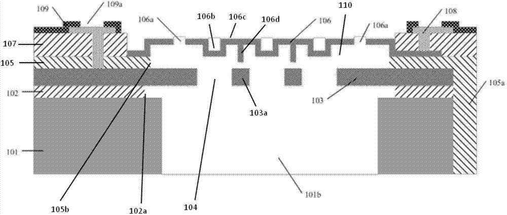
[0045] In the following specific embodiments of the present invention, please refer to figure 1 , figure 1 It is a structural schematic diagram of a MEMS micro...


PUM

PropertyMeasurementUnit
Thicknessaaaaaaaaaa
Thicknessaaaaaaaaaa
Thicknessaaaaaaaaaa

Abstract

The invention discloses an MEMS microphone with a fold-type vibrating film and a manufacturing method of the microphone. A medium sacrifice layer with a concave-convex surface is used, the vibrating film with the corresponding concave-convex fold structure is formed on the medium sacrifice layer, so that the internal stress of the vibrating film is released, the rigidity of the vibrating film is lowered, and the flexibility of the microphone is increased. The vibrating film is provided with an anti-adhesion protruding structure which can prevent the vibrating film from being adhered to a back plate in a damp environment. The layered aligning marks of the back plate are used for aligning during back cavity forming, a double-face aligning photo-etching machine is not needed, the manufacturing process is allowed to be more compatible with a CMOS process, microphone structure precision is guaranteed, and the manufacturing microphone is simple in process, high in process consistency, low in manufacturing cost, and high in flexibility.

Description

technical field [0001] The invention relates to the technical field of integrated circuit micro-electro-mechanical systems (MEMS), and more particularly, relates to a structure of a MEMS microphone with a corrugated vibrating membrane and a manufacturing method thereof. Background technique [0002] Microphones are divided into dynamic microphones and condenser microphones. The traditional dynamic microphone consists of a coil, a diaphragm and a permanent magnet. It is based on the principle that the movement of the coil in a magnetic field generates an induced current; while the main structure of a capacitive microphone is two capacitive plates, namely the diaphragm (Diaphragm ) and the backplate (Backplate), which are insulated and isolated by the air gap in the middle. Its working principle is that the sound pressure causes the deformation of the vibrating membrane, which changes the distance between the two plates of the vibrating membrane and the back plate, resulting ...

Claims


Application Information

Patent Timeline
IPC IPC(8): H04R7/12H04R19/04H04R31/00
Inventor 袁超康晓旭
Owner SHANGHAI INTEGRATED CIRCUIT RES & DEV CENT
Why Eureka
Try Eureka