
High-energy beam-ultrasonic composite additive manufacturing method for metal materials

An additive manufacturing and metal material technology, applied in the field of metal material additive manufacturing, can solve the problems of difficulty in melting additive manufacturing, small size of parts, cracking, etc., to eliminate internal stress and internal defects, low-cost rapid manufacturing, Simple processing steps

Inactive Publication Date: 2015-04-22
BEIJING INSTITUTE OF TECHNOLOGYGY
View PDF4 Cites 50 Cited by
  • Summary
  • Abstract
  • Description
  • Claims
  • Application Information

AI Technical Summary

Problems solved by technology

[0003] However, the melting and additive manufacturing of metal materials is very difficult. There are three main problems that have restricted the development and application of this technology.
First, the problem of internal stress
The thermal stress, tissue stress and solidification shrinkage stress in the metal melting additive manufacturing process cause huge internal stress in the structural parts, which makes the structural parts easy to warp, deform or even crack
Second, metallurgical defects
During the melting / solidification process of additive manufacturing, internal defects such as pores and lack of fusion are prone to occur, resulting in poor key mechanical properties such as fatigue properties of components
Third, the problem of coarse grain
However, there are certain limitations in post-processing, such as the inability to prevent deformation and cracking of parts during additive manufacturing, the inability to refine grains, the expensive hot isostatic pressing equipment, and some metallurgical defects remaining after processing
In addition, the small part size that HIP equipment can handle limits the application of high-energy beam additive manufacturing of large metal components
Therefore, post-processing is still unable to solve the three major bottlenecks in the additive manufacturing of metal components, and it is urgent to develop new methods

Method used


Image

  • High-energy beam-ultrasonic composite additive manufacturing method for metal materials
  • High-energy beam-ultrasonic composite additive manufacturing method for metal materials

Examples


Embodiment 1

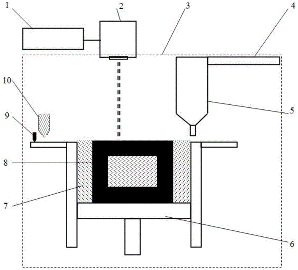
[0023] figure 1 An embodiment of the present invention is shown; a schematic diagram of a selective laser melting-ultrasonic impact composite additive manufacturing device, and the specific operation includes the following steps:

[0024] (1) The scraper 9 scrapes the metal powder 7 dropped from the powder storage box 10 onto the working plate of the forming cylinder 6 to form a pre-paved powder layer of a certain thickness;

[0025] (2) The laser 1 generates a laser beam, and selectively melts the pre-laid metal powder 7 through the scanning galvanometer 2 according to the planned cross-sectional scanning path;

[0026] (3) After the laser scanning melts / solidifies a certain number of layers, the ultrasonic impact gun 5 is driven by the mechanical device 4 to move to the working area to impact the entire surface of the solidified layer according to the set impact frequency, impact force and planned path;

[0027] (4) The ultrasonic impact gun 5 returns to the initial positio...

Embodiment 2

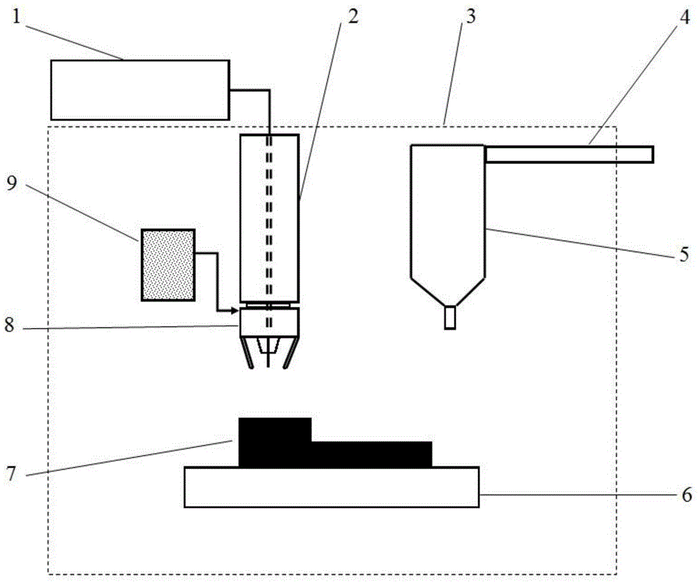
[0030] figure 2 Another specific embodiment of the present invention is shown; a schematic diagram of laser rapid prototyping-ultrasonic impact composite additive manufacturing device, and the specific operation includes the following steps:

[0031] (1) The focusing lens system 2 and the coaxial nozzle 8 are moved to the working area above the substrate 6;

[0032] (2) The laser 1 generates a laser beam with a certain spot diameter through the focusing lens system 2 to melt the substrate 6 or the surface of the formed layer 7 to form a molten pool. At the same time, the powder feeder 9 uses the protective gas to transport the metal powder, and sprays the metal powder into the molten pool through the coaxial nozzle 8, thereby melting / solidifying to form a solidified layer;

[0033] (3) After the laser melts / solidifies a certain number of layers according to the planned scanning path, the focusing lens system 2 and the coaxial nozzle 8 return to the initial position, and incr...

Embodiment 3

[0038] This embodiment has the same characteristics as Embodiment 1 except the following: the laser 1 is an electron beam emitting device.


PUM


Abstract

The invention discloses a high-energy beam-ultrasonic composite additive manufacturing method for metal materials and belongs to the field of additive manufacturing (3D printing) of metal materials. The method comprises the steps that based on the technical principle of layer-by-layer accumulation of additive manufacturing, metal forming materials are melted through high-energy beams; after the metal forming materials are melted / solidified layer by layer to accumulate to a certain number of layers, the solidified layers are subjected to ultrasonic peening to have compressive plastic deformation, so the internal stress and the internal defects of formed parts are eliminated, and crystalline grains are refined; afterwards, the process of layer-by-layer melting / solidifying accumulation and the process of ultrasonic peening are continued until the whole forming process of metal members is completed. According to the method, real-time layer-by-layer treatment is performed on the solidified layers through ultrasonic peening, so the internal stress and the internal defects can be effectively reduced or eliminated, the crystalline grains can be refined, and the mechanical property of the metal members through additive manufacturing can be improved.

Description

technical field [0001] The invention belongs to the field of metal material additive manufacturing (3D printing), in particular to a metal material high energy beam-ultrasonic composite additive manufacturing method. Background technique [0002] Additive manufacturing technology is a near-net shape manufacturing technology that uses high-energy beams to melt / solidify metal materials (powder, wire or plate) layer by layer according to the CAD model under computer control, and directly accumulates metal components layer by layer from a three-dimensional model. . Compared with traditional manufacturing methods, it does not require molds, has a short production cycle, high material utilization rate, and can be formed. Traditional methods cannot manufacture complex / ultra-complex structural parts. It has huge development potential and broad application prospects, so it has attracted much attention in recent years. . [0003] However, the melting and additive manufacturing of me...

Claims


Application Information

Patent Timeline
Patent Type & Authority Applications(China)
IPC IPC(8): B22F3/105
CPCY02P10/25
Inventor 刘长猛石学智马树元
Owner BEIJING INSTITUTE OF TECHNOLOGYGY
Learn More