Purified gas treatment process of sulfur recovery device

A treatment process and sulfur recovery technology, which is applied in the preparation/purification of sulfur, chemical instruments and methods, separation of dispersed particles, etc., can solve the problems of reducing the temperature of the reaction furnace, increasing the energy consumption of the device, and achieving the effect of reducing the SO2 content

Inactive Publication Date: 2015-04-29
CHINA PETROLEUM & CHEM CORP
View PDF8 Cites 50 Cited by
  • Summary
  • Abstract
  • Description
  • Claims
  • Application Information

AI Technical Summary

Problems solved by technology

but generate NH 4 HSO 3 and (NH 4 ) 2 SO 3 After atomization, it is introduced into the Claus reactor...

Method used


Image

  • Purified gas treatment process of sulfur recovery device
  • Purified gas treatment process of sulfur recovery device

Examples


Embodiment 1

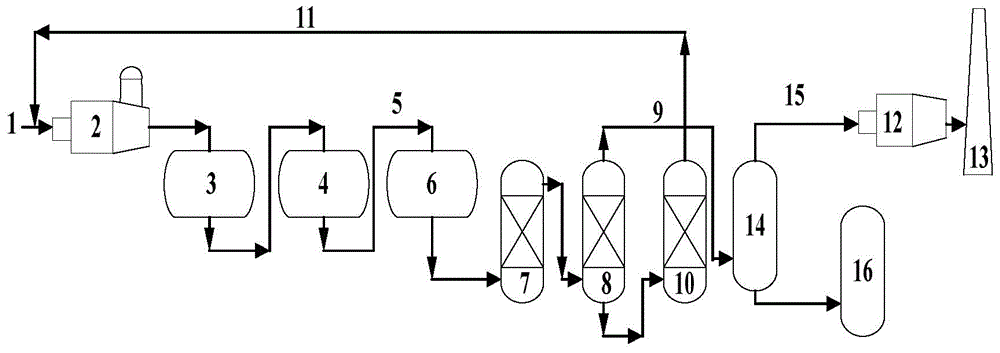
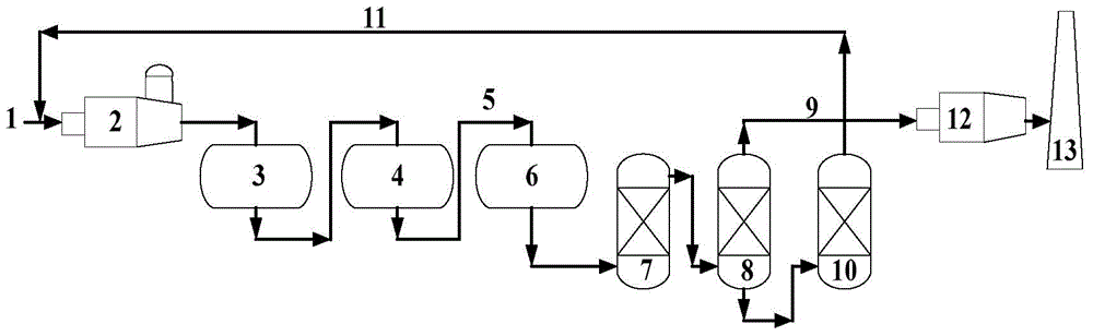
[0043] process such as figure 1 As shown, it includes thermal reaction stage, catalytic reaction stage and exhaust gas purification treatment stage.

[0044] 1) Thermal reaction stage:

[0045] Contains H 2 S90 (v / v)% acid gas (1) is partially combusted into SO in the reactor (2) 2 , at high temperature 1250°C H 2 S and SO 2 A Claus reaction occurs to form elemental sulfur and process gas. The volume content of sulfur compounds in the process gas is: H 2 S: 6%, SO 2 : 2.5%, organic sulfur: 0.5%.

[0046] 2) Catalytic reaction stage:

[0047] The tail gas of the reaction furnace enters the primary converter (3) of the catalytic reaction section (reaction conditions: temperature 320°C, space velocity 800h -1 ) and secondary converter (4) (reaction conditions: temperature 250°C, space velocity 800h -1 ), after Claus catalytic conversion, the reacted Claus tail gas (5) enters the tail gas purification unit. The volume content of sulfur compounds in Claus tail gas is: H ...

Embodiment 2

[0052] process such as figure 1 As shown, it includes thermal reaction stage, catalytic reaction stage and exhaust gas purification treatment stage.

[0053] 1) Thermal reaction stage:

[0054] Contains H 2 S84 (v / v)% acid gas (1) is partially combusted into SO in the reactor (2) 2 , at high temperature 1250°C H 2 S and SO 2 A Claus reaction occurs to form elemental sulfur and process gas. The volume content of sulfur compounds in the process gas is: H 2 S: 5.7%, SO 2 : 2.3%, organic sulfur: 0.4%.

[0055] 2) Catalytic reaction stage:

[0056] The tail gas of the reaction furnace enters the primary converter (3) of the catalytic reaction section (reaction conditions: temperature 300°C, space velocity 800h -1 ) and secondary converter (4) (reaction conditions: temperature 250°C, space velocity 800h -1 ), after Claus catalytic conversion, the reacted Claus tail gas (5) enters the tail gas purification unit. The volume content of sulfur compounds in Claus tail gas is: ...

Embodiment 3

[0061] Except following difference, other is with embodiment 2.

[0062] 3) Exhaust gas purification treatment stage:

[0063] The lye tank (14) is equipped with a concentration of 10% sodium hydroxide solution to purify tail gas H 2 S content is 4mg / m 3 .

[0064] The device for the harmless treatment of waste lye in the lye tank is the alkali slag biological treatment device: alkali slag index: sulfide 8000ppm, CODCr300000mg / L. Indicators after waste lye treatment: effluent CODCr: 420mg / L, ammonia nitrogen 9mg / L.


PUM


Abstract

The invention relates to a purified gas treatment process of a sulfur recovery device. The purified gas treatment process comprises a thermal reaction phase, a catalytic reaction phase and a tail gas purifying treatment phase, wherein in the tail gas purifying treatment phase, the Claus tail gas generated in the catalytic reaction phase is sequentially subjected to a hydrogenation reaction, cooling in a rapid quenching tower and amine liquid absorption, then the purified tail gas is fed to alkali liquor to be subjected to H2S removal treatment, and the tail gas removed from H2S is combusted and then discharged; the amine liquid amine-rich liquid absorbing H2S is fed to a regeneration tower to be regenerated, the regenerated acid gas is mixed with the acid gas, and then returned to the thermal reaction phase to further recover elemental sulfur; the exhausted lye removed from H2S is subjected to caustic dross biological treatment or acidic water stripping treatment. With adoption of the purified gas treatment process disclosed by the invention, H2S in the purified gas can be removed to 5 mg/m<3> below, the SO2 content in the smoke is obviously reduced within the reduction range of 100-1000 mg/m<3>; the exhausted lye treatment method is further provided, and the exhausted lye is subjected to the caustic dross biological treatment or the acidic water stripping treatment, so that pollution can be reduced.

Description

technical field [0001] The invention belongs to the technical field of sulfur recovery, and in particular relates to a purification gas treatment process of a sulfur recovery device. Background technique [0002] With the development of society, the problem of environmental pollution has become a restrictive factor for the rapid economic development, and it is an important and indispensable content of the legislation of governments in various countries. Industrially developed countries have very strict requirements on sulfur emissions. The United States Federal Government Environmental Protection Agency regulations stipulate that industrial heating furnace flue gas, sulfur tail gas and catalytic cracking regeneration flue gas SO 2 The emission concentration limit is 50ppm (v), equivalent to about 143mg / m 3 . [0003] Currently, flue gas SO from sulfur recovery plants in China 2 The emission concentration implements GB16297-1996 "Comprehensive Emission Standard of Air Poll...

Claims


Application Information

Patent Timeline
IPC IPC(8): C01B17/04B01D53/52
Inventor 王昌岭郭绍宗刘爱华刘剑利王群梁守江
Owner CHINA PETROLEUM & CHEM CORP
Why Eureka
Try Eureka