Method and device for comprehensively controlling parameters of high-adaptability optical fiber vibration sensing system
A fiber-optic vibration and sensing system technology, used in measuring devices, instruments, measuring ultrasonic/sonic/infrasonic waves, etc., can solve problems such as non-adaptive, single adjustment, and complex algorithms
- Summary
- Abstract
- Description
- Claims
- Application Information
AI Technical Summary
Problems solved by technology
Method used
Image
Examples
Embodiment 1
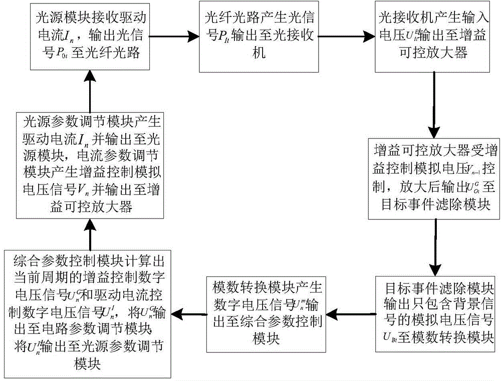
[0083] A highly adaptable optical fiber vibration sensing system parameter comprehensive control method, the light source module generates an optical signal and outputs it to the optical fiber optical path, the power of the optical signal P 0t for:
[0084] P 0t =A(I n -I th ),(n-1)T≤t
[0085] Where t is the moment, T is the cycle of overvoltage threshold rate detection, T=10us, n is the cycle number, n=1, 2, 3,..., and satisfy [] represents the rounding down function, I n is the driving current of the light source module in the nth cycle, and the driving current I of the light source module in the first cycle 1 is the initial value of the system, I 1 =100mA, I th is the threshold current of the light source module, I th =70mA, and I n >I th , A is the current conversion efficiency of the light source module, A=7W / A.
[0086] The optical fiber optical path generates an optical signal P It, and output to the optical receiver, where P It for:
[0087] P It =P...
Embodiment 2
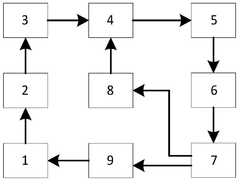
[0123] A highly adaptable optical fiber vibration sensing system parameter comprehensive control device, comprising: a light source module 1 and a comprehensive parameter control module 7,
[0124] The output interface of the light source module 1 is connected to the optical fiber optical circuit 2, and is connected to the input interface of the optical fiber optical circuit 2, and the output interface of the optical fiber optical circuit 2 is connected to the optical receiver 3, and is connected to the optical fiber optical circuit 2. The input interface of optical receiver 3 is connected, and the output interface of described optical receiver 3 is connected with gain controllable amplifier 4, and is connected with the signal input interface of described gain controllable amplifier 4, and described gain can be The output interface of control amplifier 4 is connected with target event filtering module 5, and is connected with the input interface of described target event filter...
PUM
| Property | Measurement | Unit |
|---|---|---|
| Resistance | aaaaa | aaaaa |
| Capacitance | aaaaa | aaaaa |
| Resistance | aaaaa | aaaaa |
Abstract
Description
Claims
Application Information
 - R&D
- Intellectual Property
- Life Sciences
- Materials
- Tech Scout
- Unparalleled Data Quality
- Higher Quality Content
- 60% Fewer Hallucinations
Browse by: Latest US Patents, China's latest patents, Technical Efficacy Thesaurus, Application Domain, Technology Topic, Popular Technical Reports.
© 2025 PatSnap. All rights reserved.Legal|Privacy policy|Modern Slavery Act Transparency Statement|Sitemap|About US| Contact US: help@patsnap.com


