
Solar cell with phase grating nanostructure

A technology of solar cells and phase gratings, applied in the field of solar cells

Active Publication Date: 2015-04-29
ZHEJIANG UNIV
View PDF6 Cites 10 Cited by
  • Summary
  • Abstract
  • Description
  • Claims
  • Application Information

AI Technical Summary

Problems solved by technology

But the photoelectric conversion efficiency limit of silicon solar cells is only 24%.

Method used


Image

  • Solar cell with phase grating nanostructure
  • Solar cell with phase grating nanostructure
  • Solar cell with phase grating nanostructure

Examples


Embodiment Construction

[0042] The present invention will be further described below in conjunction with drawings and embodiments.

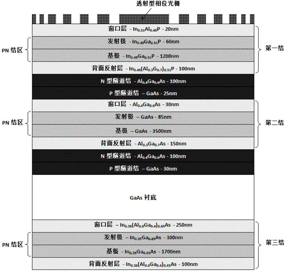
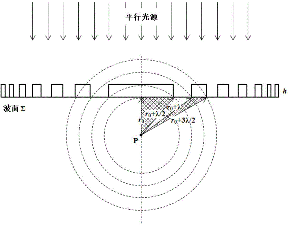
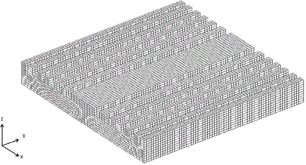
[0043] Such as figure 1 As shown, the present invention includes a solar cell; it is characterized in that: a transmission type phase grating is made on the upper surface of the solar cell, the phase grating is formed by a series of etched grooves, and the depth of the etched groove is given by the formula h=λ / [2(n-1)] is calculated so that the phase difference of the incident light propagating from the upper surface of the grating to the lower surface is π, where λ is the central wavelength of the incident light, and n is the refractive index of the phase grating material on the surface of the solar cell; The width and interval of the etching grooves are designed according to the Huygens-Fresnel principle and calculated by the Fresnel wave band method.

[0044]The depth of the etching groove is 1 / 4 of the central wavelength of the incident light, so that the phase di...


PUM


Abstract

The invention discloses a solar cell with a phase grating nanostructure. A transmission type phase grating is manufactured on the surface of the solar cell, wherein the phase grating is composed of a series of etching grooves, the depth of the etching grooves is calculated through the formula h=lambda / [2(n-1)], pi represents the phase difference generated when incident light is spread to the lower surface from the upper surface of the grating, lambda represents the central wavelength of the incident light, and n represents the refractive index of materials of the phase grating on the surface of the solar cell. The width and interval of the etching grooves are designed according to the Huygens-Fresnel principle and calculated through the Fresnel wave band method. By means of the integration of the phase grating and the solar cell, a high-performance, small-size and high-efficiency photovoltaic system is obtained. The reflectivity of the surface of the solar cell can be effectively decreased. The absorption length of photons in PN junction areas of the solar cell is effectively increased. The light field density of the incident light in the PN junction areas of the solar cell is effectively increased; the effective photon absorption of the PN junction areas of the solar cell is effectively increased.

Description

technical field [0001] The invention relates to a solar cell, in particular to a solar cell with a phase grating nanostructure. Background technique [0002] Photovoltaic power generation has always been a clean energy solution that has attracted much attention, and solar cells are currently one of the most dynamic research fields. Solar cells rely on the photovoltaic effect to realize the effective use of solar energy. After nearly a century of development, solar cells have gone through three generations. The first generation is a crystalline solar cell based on silicon materials, and the second generation includes amorphous silicon, poly Thin-film cells made of polycrystalline silicon, cadmium telluride (CdTe), copper indium gallium selenide (CIGS) and other materials, the third generation is a new type of high conversion rate solar cell, including multi-junction (multi-junction or tandem) , intermediate band, carrier-multiplication, and photon energy conversion (prior up...

Claims


Application Information

Patent Timeline
Patent Type & Authority Applications(China)
IPC IPC(8): H01L31/054H01L31/0687H01L31/0693
CPCY02E10/52Y02E10/544H01L31/0687H01L31/0693
Inventor 柳楠何建军
Owner ZHEJIANG UNIV
Learn More